This is my home-built, 8-segment, ramp/soak kiln controller. I built this controller to automate a couple of old kilns I use for melting and
fusing glass to make my own telescope mirrors. The kilns are old, and they were designed for
firing ceramics. Clay isn't as demanding as glass. The built-in controllers on the old kilns are rudimentary. They couldn't handle keeping glass within a
degree or two of a target temperature for long periods for annealing purposes, or doing a very slow ramp-down in temperature over several days
needed to cool thick glass castings safely. I also wanted to automate as much as possible of the firing, and not have to baby-sit the kilns
any more than necessary. So I built my own ramp/soak controller.
This project came together rather quickly and easily, and it didn't cost a whole lot, because I already had a most of the parts in my well stocked
workshop. The parts I didn't have were purchased cheap at a laboratory equipment auction.
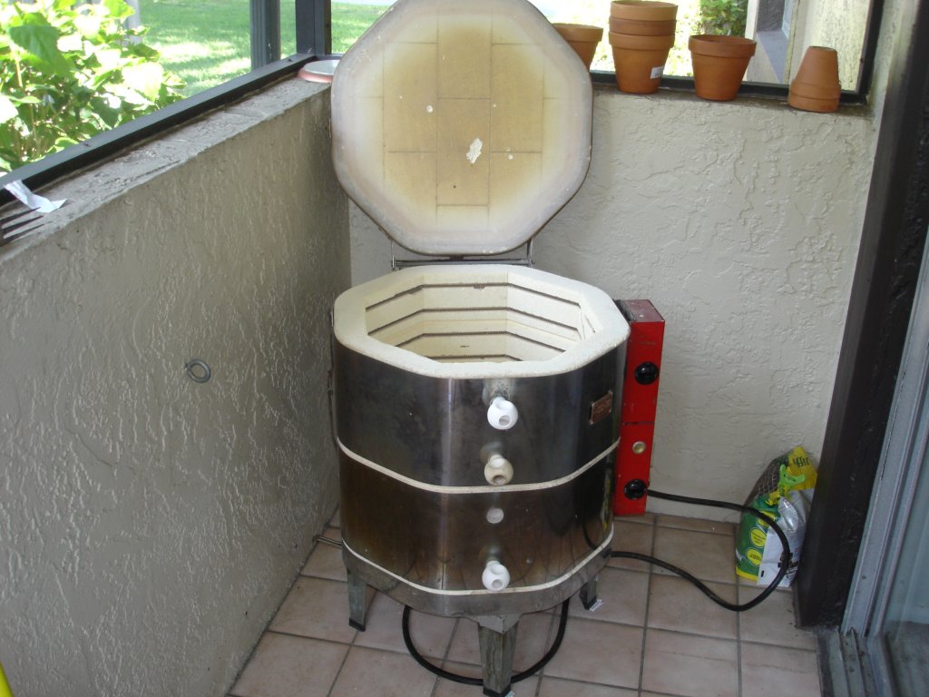
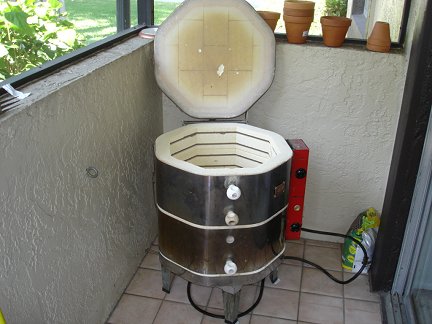 Here is one of my kilns. It is an older model Skutt high-fire ceramic kiln. This is the kiln I do most of my glass fusing and casting in because it is
large enough to make telescope mirrors up to 16 inches in diameter. I found this kiln in a Craig's List ad, and bought it cheap. Even though it is old,
and a little beat-up, it still works great. The problem is that the controls, (not easily visible in this photo), are simply knobs with settings of
Low, Medium, High and Off for each segment of the kiln. That is not much control. A mechanism that detects the softening of a pyrometric cone would
kill the power to the kiln when the desired temperature was reached. This primitive system may work for firing ceramics, but it is totally inadequate
for working with glass.
Here is one of my kilns. It is an older model Skutt high-fire ceramic kiln. This is the kiln I do most of my glass fusing and casting in because it is
large enough to make telescope mirrors up to 16 inches in diameter. I found this kiln in a Craig's List ad, and bought it cheap. Even though it is old,
and a little beat-up, it still works great. The problem is that the controls, (not easily visible in this photo), are simply knobs with settings of
Low, Medium, High and Off for each segment of the kiln. That is not much control. A mechanism that detects the softening of a pyrometric cone would
kill the power to the kiln when the desired temperature was reached. This primitive system may work for firing ceramics, but it is totally inadequate
for working with glass.
I also have a smaller Duncan kiln that I used for my early fusing experiments, and still occasionally use for smaller jobs. Its built-in controller is
not much more capable than that of the Skutt kiln. It caused me much frustration and ruined a lot of glass in those early experiments. That is when I
determined I was going to build a ramp/soak controller capable of running either kiln.
So what is a ramp/soak controller? Briefly, this controller allows the kiln temperature to be ramped up or down at a programmable rate. That is the ramp
part. The soak part means that I can program the kiln to hold a certain temperature very precisely, and soak the material in the kiln at that temperature
for a programmable period of time. So basically this controller allows me to program up a firing schedule consisting of multiple ramps and soaks. This is
just what is needed for working with glass. Glass is finicky. Heat it up or cool it down too quickly and it will shatter. If glass is heated above a certain
temperature, it must go through an anneal soak and very slow cool-down or massive amounts of strain will be incorporated into the glass. So a ramp/soak controller
is a must have for working with glass. This controller allows me to program a firing schedule with up to eight ramp and soak segments. I rarely need that many.
 Here is the brain of the controller. It is an Omega Engineering CN8201 Series Universal Temperature & Process Controller with 8 Segment Ramp/Soak Capability.
I was lucky enough to get this unit as part of a box lot of laboratory equipment I bought for $10 at an auction. It sells for about $360 new from Omega.
Here is a link to the unit on Omega's web site where you can find a full description of its
functions and capabilities. I have seen similar cheap Chinese knockoff controllers for sale on eBay and other places for less than $100.
I love this controller. I just wish it was the model with RS-232 serial communication. That would allow me to program and
control it remotely from my computer. As it is, I have to enter all the program steps and send commands to it from the four button interface on the front panel.
Oh well. I got it really cheap, and now that I am quite familiar with how to do it, entering the programs isn't too much of a chore.
Here is the brain of the controller. It is an Omega Engineering CN8201 Series Universal Temperature & Process Controller with 8 Segment Ramp/Soak Capability.
I was lucky enough to get this unit as part of a box lot of laboratory equipment I bought for $10 at an auction. It sells for about $360 new from Omega.
Here is a link to the unit on Omega's web site where you can find a full description of its
functions and capabilities. I have seen similar cheap Chinese knockoff controllers for sale on eBay and other places for less than $100.
I love this controller. I just wish it was the model with RS-232 serial communication. That would allow me to program and
control it remotely from my computer. As it is, I have to enter all the program steps and send commands to it from the four button interface on the front panel.
Oh well. I got it really cheap, and now that I am quite familiar with how to do it, entering the programs isn't too much of a chore.
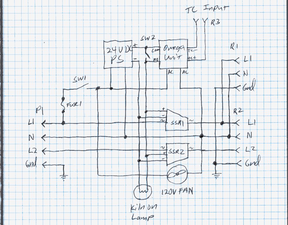
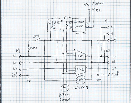 Here is a schematic of the controller unit. Click the photo for a larger view. The Omega unit may be the brains of the controller, but it needs other
parts to act as muscles and do the
heavy lifting of controlling the massive current the kilns draw. In this case the muscle comes from two 15A Solid State Relays, SSR1 and SSR2, that
control the current to the kiln. A 24V power supply provides power to switch the relays on, and power an indicator lamp that lights when the power to
the kiln is on. The solid state relays produce a lot of heat, so they are mounted to a large aluminum heatsink, and a fan blows air on the fins of
the heatsink. SW1 is the main power switch. SW2 allows me to bypass the Omega controller and power up the kilns anytime SW1 is on. P1 is a 4-prong
220V plug that provides power to the controller. R1 is a 3-prong receptacle that provides power for my small 120V Duncan Kiln. R2 is a 4-prong receptacle
that provides 220V power for my big Skutt kiln. Naturally I can only run one kiln at a time without overloading the controller. R3 is a receptacle for
plugging in a type-K thermocouple probe. Each of my kilns is equipped with one.
Here is a schematic of the controller unit. Click the photo for a larger view. The Omega unit may be the brains of the controller, but it needs other
parts to act as muscles and do the
heavy lifting of controlling the massive current the kilns draw. In this case the muscle comes from two 15A Solid State Relays, SSR1 and SSR2, that
control the current to the kiln. A 24V power supply provides power to switch the relays on, and power an indicator lamp that lights when the power to
the kiln is on. The solid state relays produce a lot of heat, so they are mounted to a large aluminum heatsink, and a fan blows air on the fins of
the heatsink. SW1 is the main power switch. SW2 allows me to bypass the Omega controller and power up the kilns anytime SW1 is on. P1 is a 4-prong
220V plug that provides power to the controller. R1 is a 3-prong receptacle that provides power for my small 120V Duncan Kiln. R2 is a 4-prong receptacle
that provides 220V power for my big Skutt kiln. Naturally I can only run one kiln at a time without overloading the controller. R3 is a receptacle for
plugging in a type-K thermocouple probe. Each of my kilns is equipped with one.
In operation, the Omega controller senses the temperature in the kiln, and compares it to what it should be according to where it is in the firing
schedule. If the temperature is too low, it closes an internal relay. If it is too high, the internal
relay opens. The positive line from the 24V power supply is connected to the Common side of the Omega's relay. The Normally Open side of the relay
is connected to the solid state relays and indicator lamp. This allows the Omega unit to switch the relays on and off, and thus control the kiln
temperature. I normally set the kiln temperature knobs to their highest settings, and let my controller do all the temperature control by throttling
the power to the kilns.
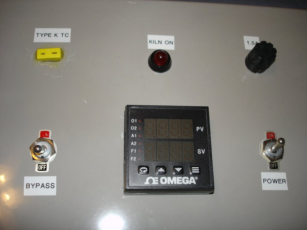
 Here is a close-up of the front panel of the kiln controller. It is built in a large, fiberglass, electrical box. The Omega controller is in the center.
At lower right is the main power switch. The bypass switch is on the lower left. A fuse holder for a 1.5 Amp fuse is on the upper right. A red 24V indicator
lamp that glows when kiln power is on is in the top center. The receptacle for a type-K thermocouple is on the upper left.
Here is a close-up of the front panel of the kiln controller. It is built in a large, fiberglass, electrical box. The Omega controller is in the center.
At lower right is the main power switch. The bypass switch is on the lower left. A fuse holder for a 1.5 Amp fuse is on the upper right. A red 24V indicator
lamp that glows when kiln power is on is in the top center. The receptacle for a type-K thermocouple is on the upper left.
Click the photo for a larger view.
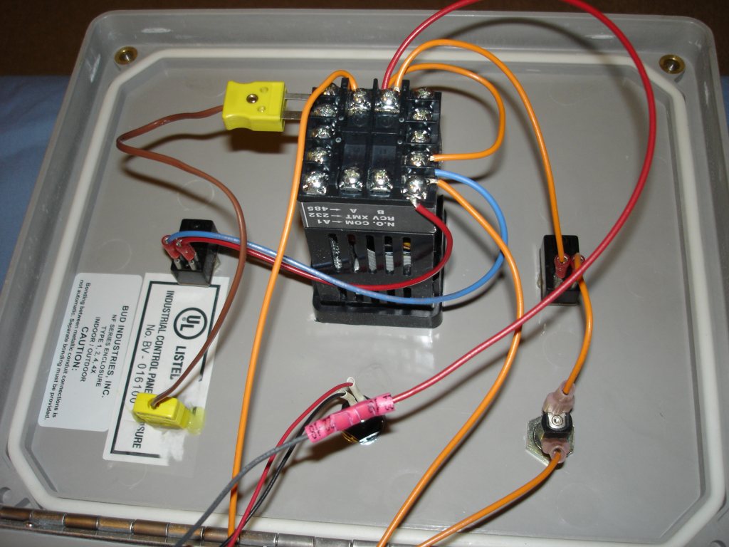
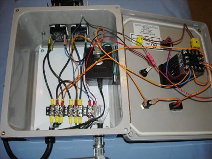 Here is a look inside the box. There really isn't much to this controller since the Omega unit does most of the work. The omega unit and front-panel
controls are mounted on the lid of the box on the right. The solid state relays, 24V power supply, and terminal block for wiring everything together are
mounted inside the box on the left.
Here is a look inside the box. There really isn't much to this controller since the Omega unit does most of the work. The omega unit and front-panel
controls are mounted on the lid of the box on the right. The solid state relays, 24V power supply, and terminal block for wiring everything together are
mounted inside the box on the left.
Click the photo for a larger view.
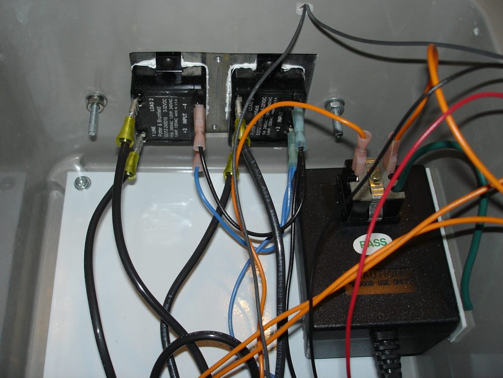
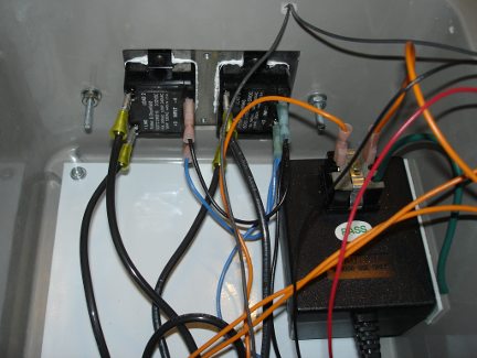 Here is a close-up showing the two solid state relays in the upper center, and the 24V wall wart power supply on the right. A large hole was cut
in the side of the fiberglass box to allow the SSRs to mount to a massive aluminum heatsink bolted to the outside of the box. Silicone heatsink
grease was used between the SSRs and the heatsink. The 24V, 1A power
supply is simply held in place with double-sided tape on the bottom and at the side. A panel-mount AC receptacle is used to connect wires to the
wall wart power supply.
Here is a close-up showing the two solid state relays in the upper center, and the 24V wall wart power supply on the right. A large hole was cut
in the side of the fiberglass box to allow the SSRs to mount to a massive aluminum heatsink bolted to the outside of the box. Silicone heatsink
grease was used between the SSRs and the heatsink. The 24V, 1A power
supply is simply held in place with double-sided tape on the bottom and at the side. A panel-mount AC receptacle is used to connect wires to the
wall wart power supply.
Click the photo for a larger view.
 Here is a view of the Omega unit and front-panel controls mounted on the underside of the lid of the box. Pretty basic stuff. Not much to see here.
One thing to note is that the wires connecting from the lid to various places inside the box had to be left extra long to allow enough slack for
the lid to swing open. That contributes to the rat's nest look of the wiring.
Here is a view of the Omega unit and front-panel controls mounted on the underside of the lid of the box. Pretty basic stuff. Not much to see here.
One thing to note is that the wires connecting from the lid to various places inside the box had to be left extra long to allow enough slack for
the lid to swing open. That contributes to the rat's nest look of the wiring.
Click the photo for a larger view.
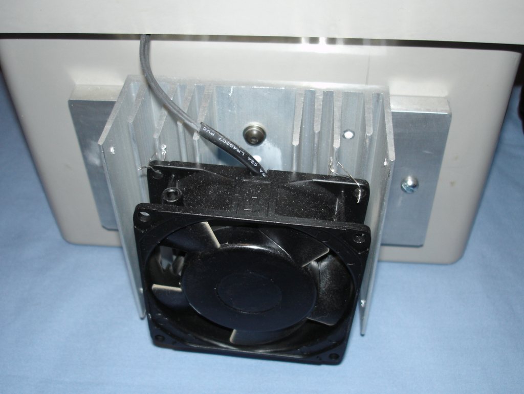
 Here is a view of the heatsink and fan mounted on the outside of the box. I made the heatsink from a massive bar of aluminum with a large finned aluminum
heatsink bolted on top of it. Silicone heatsink grease was used in the joint between the two pieces of aluminum. I mounted the fan on the heatsink by wiring
the fan in place through holes drilled in the fins of the heatsink and the fan's own mounting holes. I need to add a guard to the fan. I have got my
fingers in it a couple of times.
Here is a view of the heatsink and fan mounted on the outside of the box. I made the heatsink from a massive bar of aluminum with a large finned aluminum
heatsink bolted on top of it. Silicone heatsink grease was used in the joint between the two pieces of aluminum. I mounted the fan on the heatsink by wiring
the fan in place through holes drilled in the fins of the heatsink and the fan's own mounting holes. I need to add a guard to the fan. I have got my
fingers in it a couple of times.
Click the photo for a larger view.
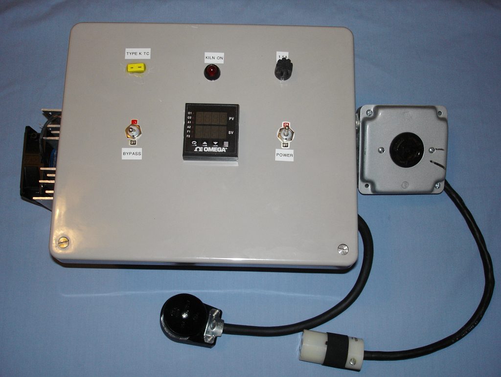
Here is an overview of the kiln controller showing its external connections. The large plug at lower center is the main 220V input plug. I use a long,
heavy-duty, RV extension cord to plug the controller into my dryer outlet. The smaller receptacle on the lower right is the 120V socket for plugging in my 120V
Duncan Kiln. The large receptacle in the metal box on the right is the 220V plug for my big Skutt kiln.
Click the photo for a larger view.
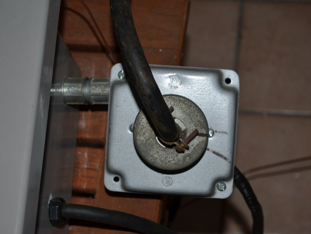
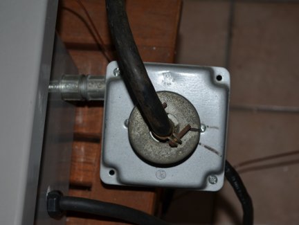 Here the big, 4-prong, twist-lock plug for my Skutt kiln is plugged into the 220V outlet mounted to the side of the controller box.
Click the photo for a larger view.
Here is a typical firing schedule I would program into the controller to
cast a telescope mirror in my kiln.
| Firing Schedule |
| Segment |
1 |
2 |
3 |
4 |
5 |
6 |
7 |
| Ramp Time |
300 |
60 |
115 |
AFAP |
2000 |
1000 |
1400 |
| Temperature |
950 |
1250 |
1750 |
1050 |
950 |
850 |
90 |
| Soak Time |
0 |
60 |
60 |
400 |
0 |
0 |
0 |
In this firing schedule I am only using seven of the eight available program segments.
Times are in minutes. Temperatures are in degrees F. AFAP = As Fast As Possible (I set the ramp time to about 5 minutes, then open
the kiln lid to get the temperature down quickly
so as not to linger in the glass devitrification zone).
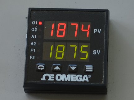
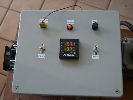 Here is a close-up shot of the kiln controller in operation. The upper red number is the current temperature in the kiln. The lower green number is the
target temperature. I'm doing an experiment here, running hotter than I usually do, to see if I can get the bubbles to rise to the surface of a piece of
glass and pop faster than they do at lower temperatures.
Here is a close-up shot of the kiln controller in operation. The upper red number is the current temperature in the kiln. The lower green number is the
target temperature. I'm doing an experiment here, running hotter than I usually do, to see if I can get the bubbles to rise to the surface of a piece of
glass and pop faster than they do at lower temperatures.
Click the photo for a larger view.
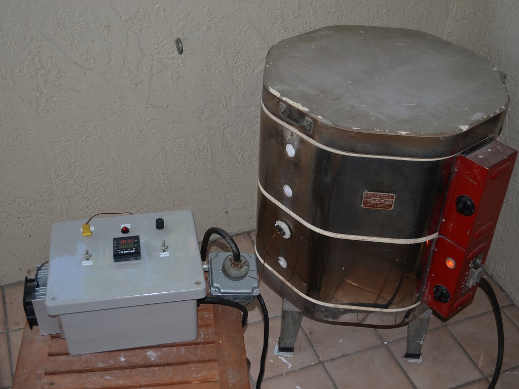
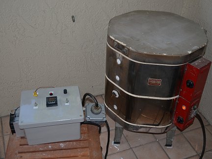 Here is a shot of the kiln controller and kiln together. This kiln controller works great! It has basically totally automated my kilns. I can
program in a firing schedule, load the kiln, start
the sequence, and then just walk away, even from a many days long firing. I don't have to babysit the kilns anymore. The only time I personally
have to intervene is if I want to quickly crash the temperature at some point in the firing by opening the kiln lid. But I can now program that to
happen at a time convenient for me, and can plan ahead for it. Very long annealing soaks at precisely controlled temperatures are now possible
for me. Days long, slow cooling ramps for thick castings are dead easy. Shotgun annealing with mystery glass is a breeze. I love this controller.
Here is a shot of the kiln controller and kiln together. This kiln controller works great! It has basically totally automated my kilns. I can
program in a firing schedule, load the kiln, start
the sequence, and then just walk away, even from a many days long firing. I don't have to babysit the kilns anymore. The only time I personally
have to intervene is if I want to quickly crash the temperature at some point in the firing by opening the kiln lid. But I can now program that to
happen at a time convenient for me, and can plan ahead for it. Very long annealing soaks at precisely controlled temperatures are now possible
for me. Days long, slow cooling ramps for thick castings are dead easy. Shotgun annealing with mystery glass is a breeze. I love this controller.
Click the photo for a larger view.
I hope this page is useful for anyone else out there who is struggling using an older kiln and wants to build a ramp/soak controller.
 Here is one of my kilns. It is an older model Skutt high-fire ceramic kiln. This is the kiln I do most of my glass fusing and casting in because it is
large enough to make telescope mirrors up to 16 inches in diameter. I found this kiln in a Craig's List ad, and bought it cheap. Even though it is old,
and a little beat-up, it still works great. The problem is that the controls, (not easily visible in this photo), are simply knobs with settings of
Low, Medium, High and Off for each segment of the kiln. That is not much control. A mechanism that detects the softening of a pyrometric cone would
kill the power to the kiln when the desired temperature was reached. This primitive system may work for firing ceramics, but it is totally inadequate
for working with glass.
Here is one of my kilns. It is an older model Skutt high-fire ceramic kiln. This is the kiln I do most of my glass fusing and casting in because it is
large enough to make telescope mirrors up to 16 inches in diameter. I found this kiln in a Craig's List ad, and bought it cheap. Even though it is old,
and a little beat-up, it still works great. The problem is that the controls, (not easily visible in this photo), are simply knobs with settings of
Low, Medium, High and Off for each segment of the kiln. That is not much control. A mechanism that detects the softening of a pyrometric cone would
kill the power to the kiln when the desired temperature was reached. This primitive system may work for firing ceramics, but it is totally inadequate
for working with glass.