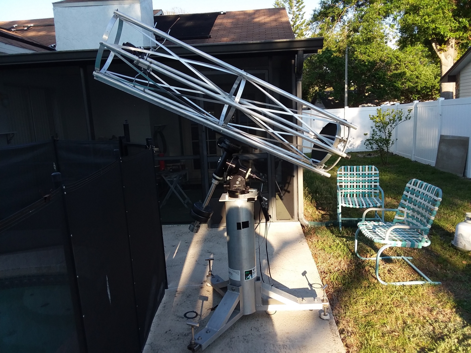
 This is a photo of the very fist time I set up my new, home-built, 12.5 inch, f/4.5 astrograph on the Losmandy G-11 mount for initial testing and first light. It was (and still is) a work in progress,
but I just had to see how well it worked.
This is a photo of the very fist time I set up my new, home-built, 12.5 inch, f/4.5 astrograph on the Losmandy G-11 mount for initial testing and first light. It was (and still is) a work in progress,
but I just had to see how well it worked.
This web page will tell the story of how this astrograph was built. I built every bit of it. I cast the primary mirror in my kiln. I ground, polished and parabolized the mirror. I learned
lost foam casting in aluminum to make part of the primary mirror cell. I built the entire structure of the astrograph out of aluminum. In fact there is so much aluminum in this scope that
I have affectionately nicknamed it Al.
Fear not, if you want to build an astrograph like this one, you can do so with off the shelf components. Things like a suitable primary mirror, mirror cell, spider support and tube can be
had commercially. You don't have to go to the lengths I did to do it all myself. That's just how I am. You'd still need some optical design and fabrication skills to put all the pieces
together and make them work, but it would be a lot quicker and easier than my way. Anyway, this is the story of how I did it. So buckle up, this is going to be quite a ride that covers
several years and involves fields such as glass casting, mirror fabrication, lost foam casting and metal fabrication among other things.
 The story starts with my desire to cast large, but light weight telescope mirror blanks. I had already been casting solid blanks for a while, when some years ago I got the idea of casting
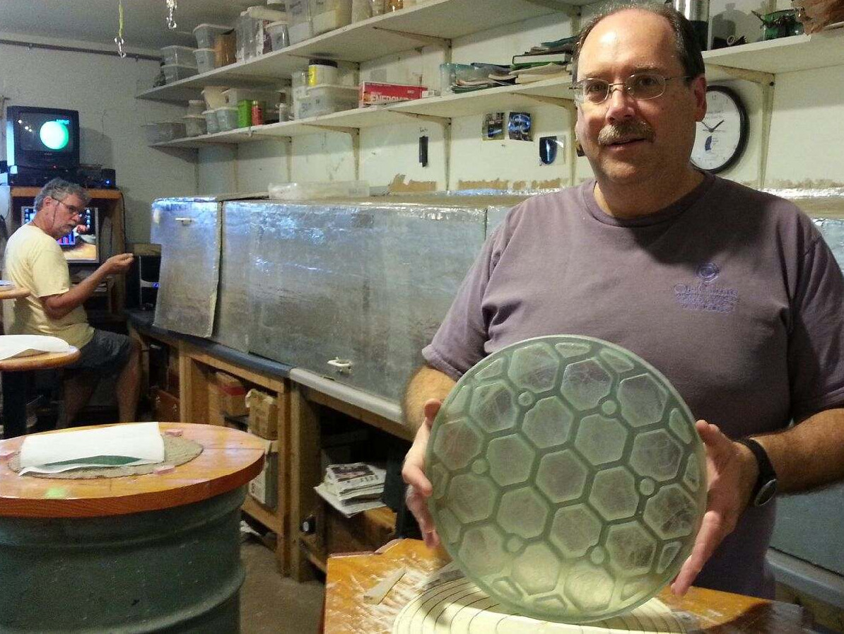
honeycomb-back mirrors to lighten the mirrors. It took a lot of tries and different iterations on the design and mold-making process, but eventually, after four generations of different designs,
I came up with a viable honeycomb-back design.
The story starts with my desire to cast large, but light weight telescope mirror blanks. I had already been casting solid blanks for a while, when some years ago I got the idea of casting
honeycomb-back mirrors to lighten the mirrors. It took a lot of tries and different iterations on the design and mold-making process, but eventually, after four generations of different designs,
I came up with a viable honeycomb-back design.
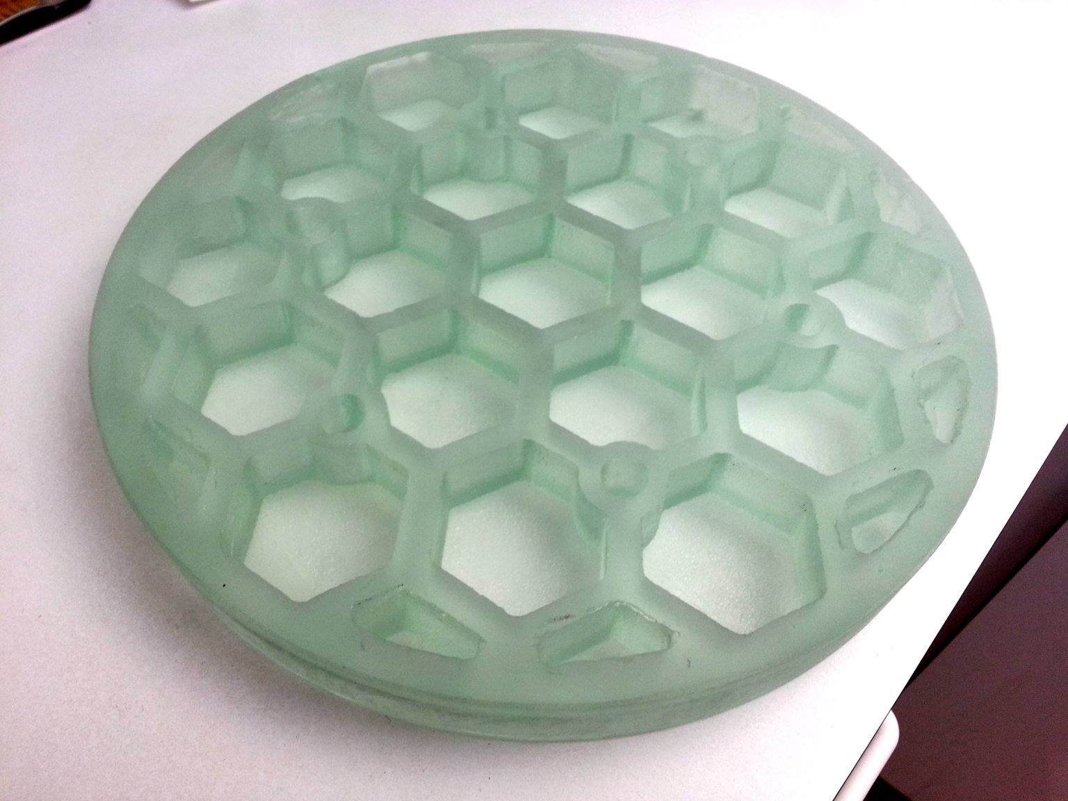
This photo shows an early mold design for a honeycomb-back mirror.
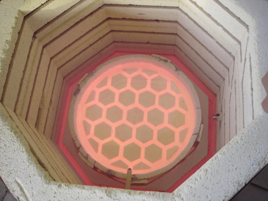 Here is a photo of one of my earlier honeycomb-back mirror designs being cast in the kiln.
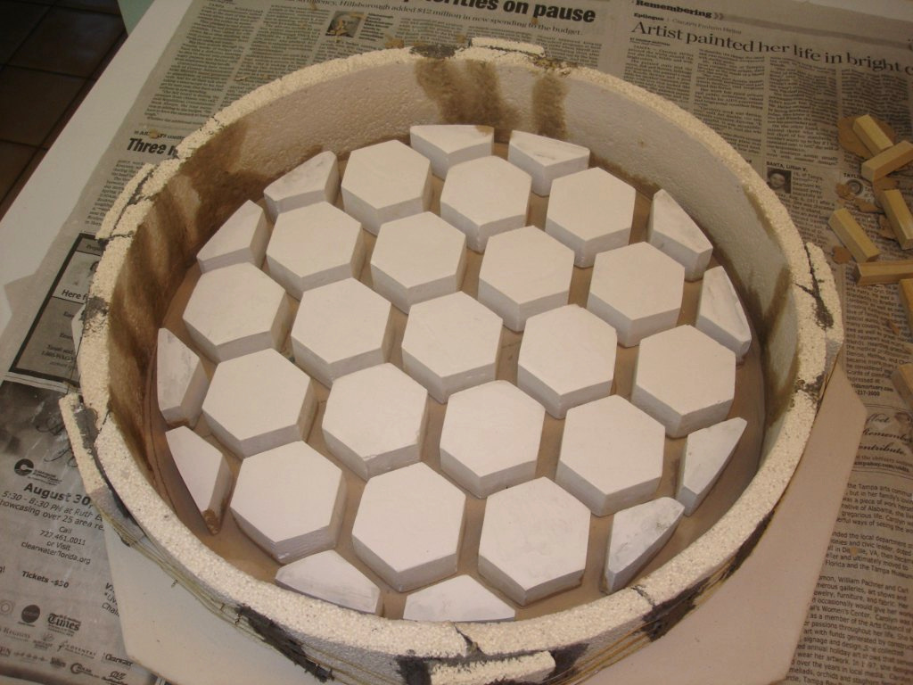
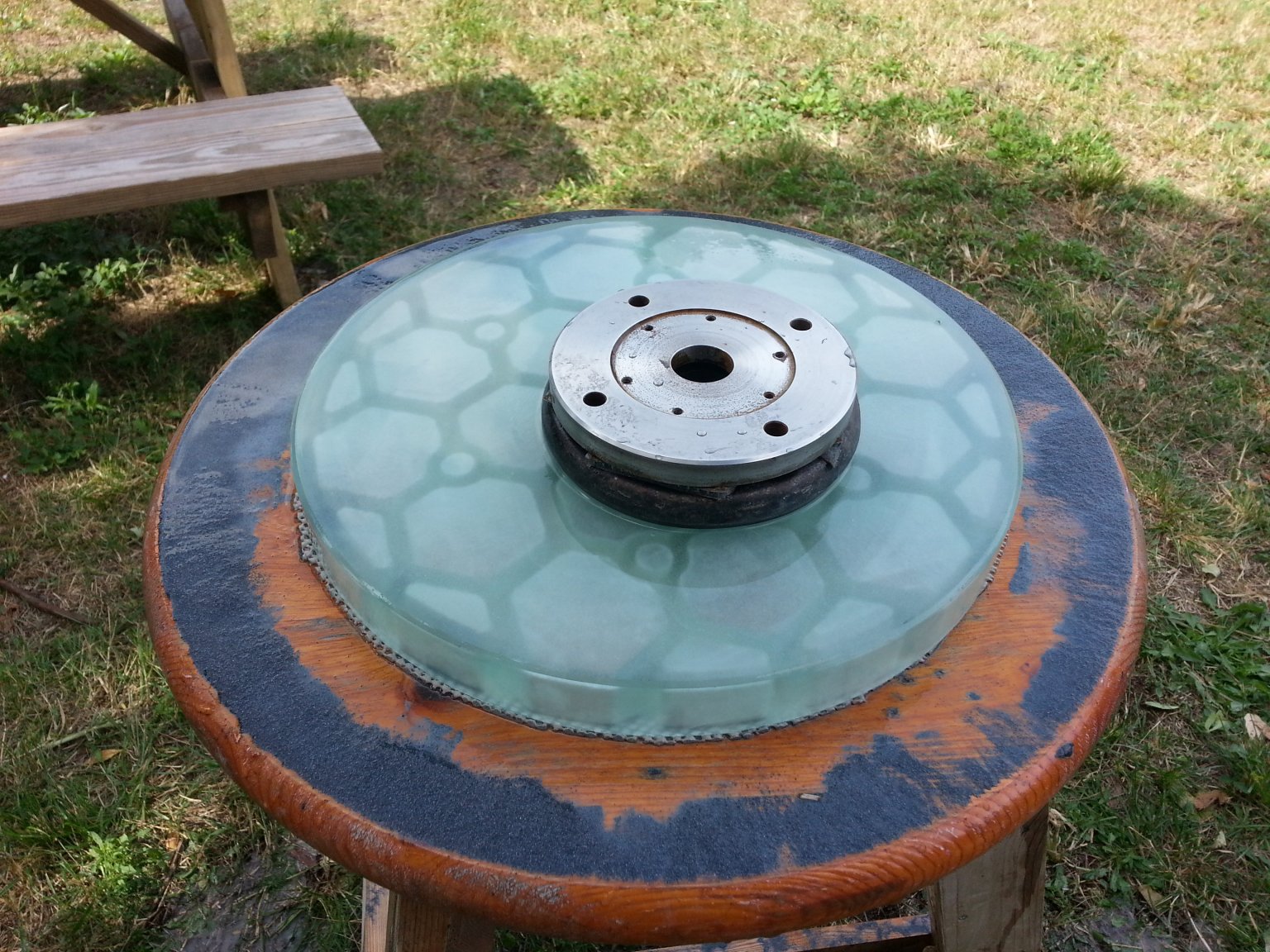
 My latest 4th generation design incorporates alignment sockets and weight-bearing pads into the glass. This greatly simplifies the mounting of the mirror. It also incorporates a constant thickness
front plate designed to match the curve of the expected ROC of the finished mirror.
My latest 4th generation design incorporates alignment sockets and weight-bearing pads into the glass. This greatly simplifies the mounting of the mirror. It also incorporates a constant thickness
front plate designed to match the curve of the expected ROC of the finished mirror.
The mirror blank only weighed a little over seven pounds before grinding! That is amazingly light for a 12.5 inch diameter blank that is 1.25 inches thick. About another half pound of glass was ground
away during rough grinding.
 In this photo I am rough grinding the curve into the mirror using a couple of barbell weights. The iron weight on the bottom is the tool doing the actual grinding. The steel weight on top
adds mass and makes things go faster. I absolutely love the barbell method for rough grinding by hand. It just goes so quickly. Later I switched to a full diameter tile tool for fine grinding.
In this photo I am rough grinding the curve into the mirror using a couple of barbell weights. The iron weight on the bottom is the tool doing the actual grinding. The steel weight on top
adds mass and makes things go faster. I absolutely love the barbell method for rough grinding by hand. It just goes so quickly. Later I switched to a full diameter tile tool for fine grinding.
 The mirror was polished with a full size pitch lap. Parabolizing was done with a variety of sub-diameter pitch laps. I had a lot of trouble with either turning the edge or digging a hole
in the center when using the full size pitch lap. The mirror had to be brought back to spherical several times and then parabolizing begun again. None of the experts at the SPAC Mirror
lab are sure why my honeycomb-back mirrors are so difficult to parabolize with full diameter laps. They always seem to need slow and careful application of a variety of sizes of sub-diameter
laps to get the job done. Anyway, all the false starts and returns to spherical, combined with some medical issues
that kept me sidelined for a while, meant that this mirror took quite a while to finish. I was one happy camper when it was finally done.
The mirror was polished with a full size pitch lap. Parabolizing was done with a variety of sub-diameter pitch laps. I had a lot of trouble with either turning the edge or digging a hole
in the center when using the full size pitch lap. The mirror had to be brought back to spherical several times and then parabolizing begun again. None of the experts at the SPAC Mirror
lab are sure why my honeycomb-back mirrors are so difficult to parabolize with full diameter laps. They always seem to need slow and careful application of a variety of sizes of sub-diameter
laps to get the job done. Anyway, all the false starts and returns to spherical, combined with some medical issues
that kept me sidelined for a while, meant that this mirror took quite a while to finish. I was one happy camper when it was finally done.
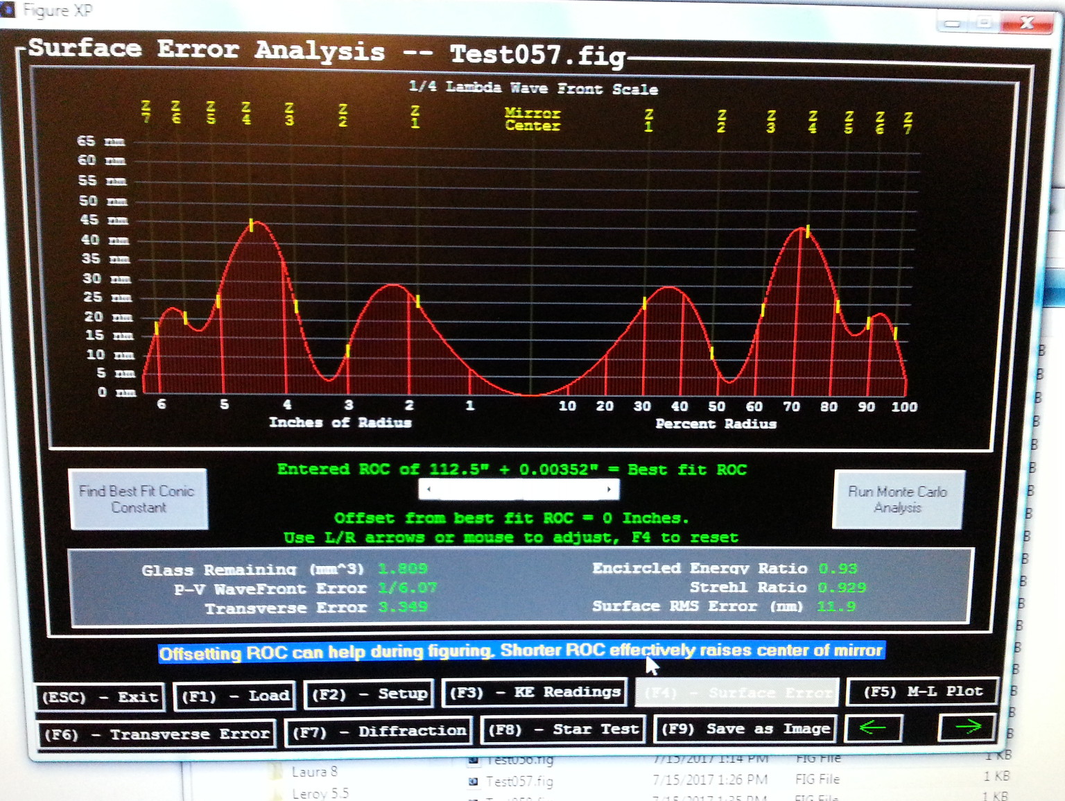 Here is Surface Error Analysis for the completed mirror. It's always tempting to try to improve it further, but this mirror was very temperamental. I vowed to stop as soon as I got it to
1/6th wave or better. There was just too much risk of screwing it up and needing to return to a sphere yet again if I kept trying to improve it further. I'm happy with it at 1/6th wave.
Here is Surface Error Analysis for the completed mirror. It's always tempting to try to improve it further, but this mirror was very temperamental. I vowed to stop as soon as I got it to
1/6th wave or better. There was just too much risk of screwing it up and needing to return to a sphere yet again if I kept trying to improve it further. I'm happy with it at 1/6th wave.
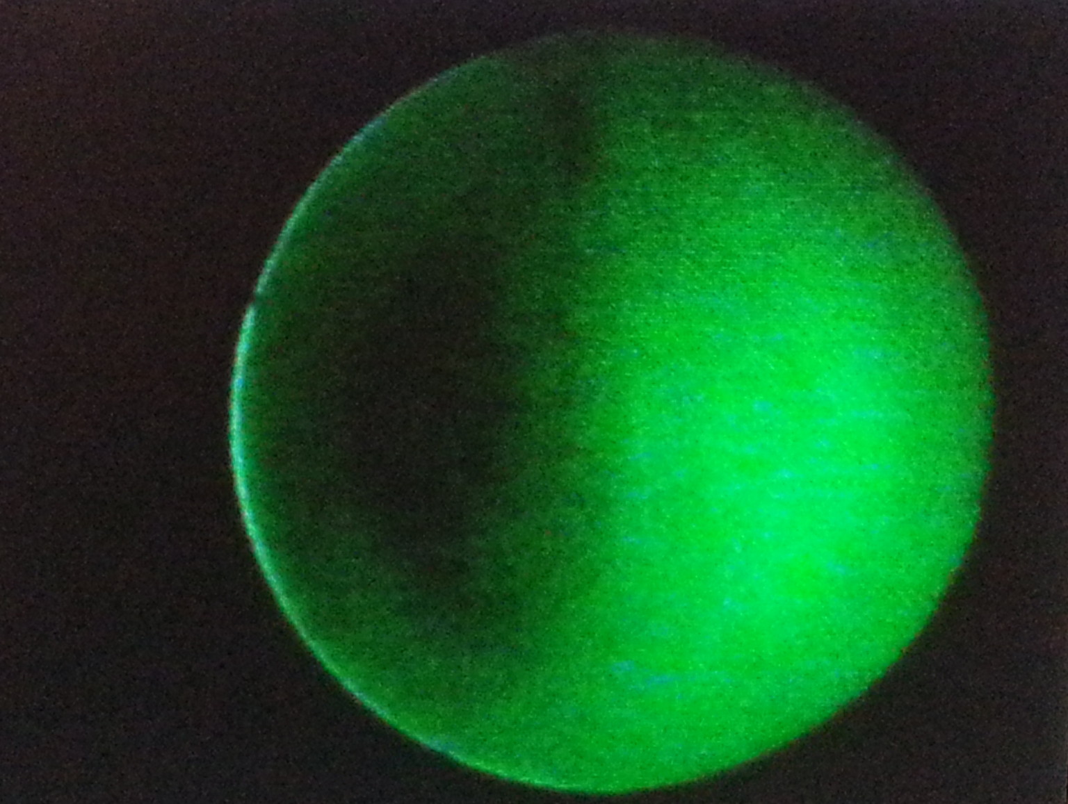 Here is a Focogram of the finished mirror. Not too shabby. I'll take it.
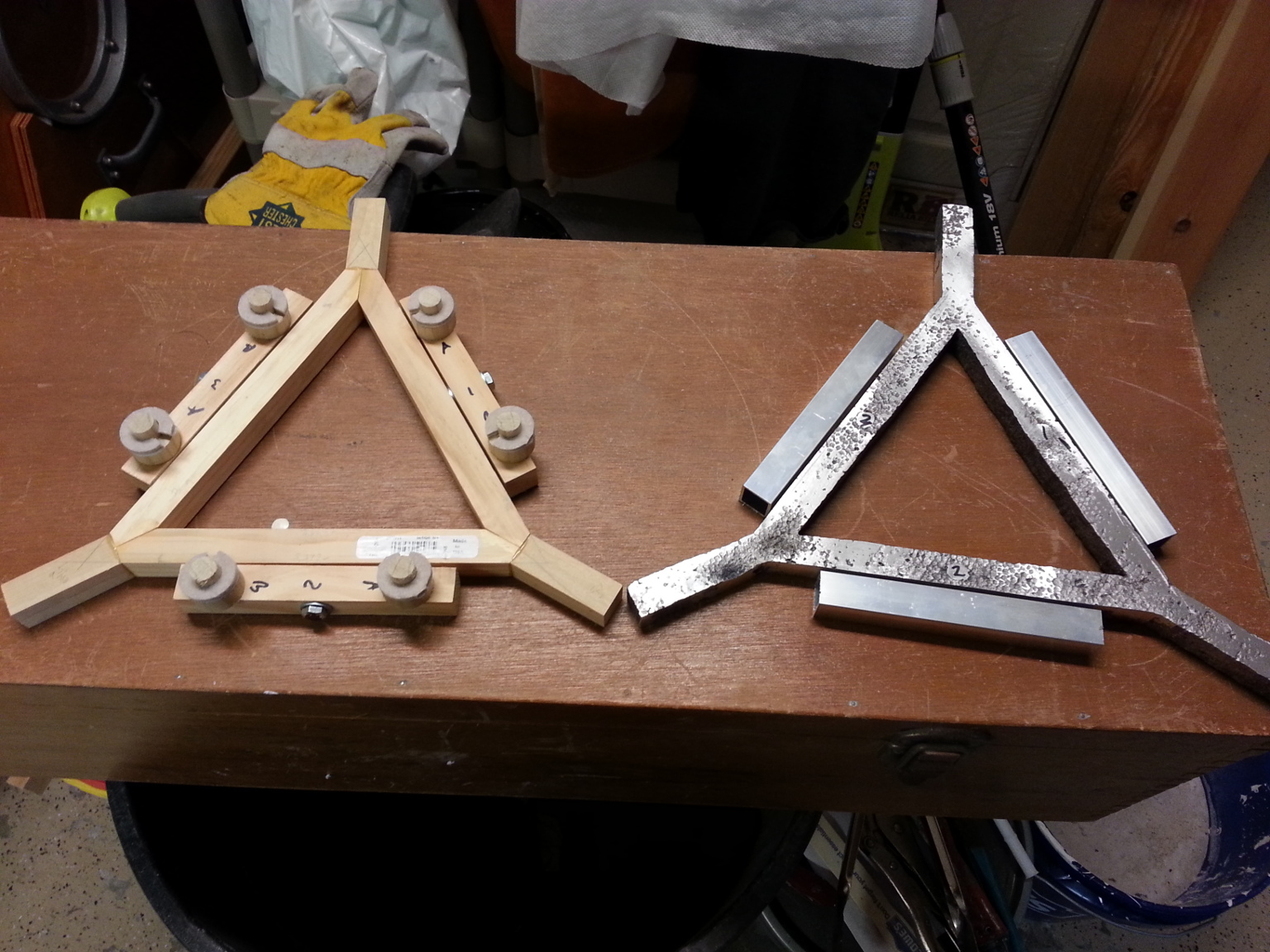 Now that I had a mirror, I needed a cell to mount it in. I had an idea of what the cell would be like when I designed the mirror. I built a mockup cell out of wood to make sure it would work.
It has six pins and support points that engage the sockets on the back of the mirror. Two pins are mounted on each of three pivoting arms. There is a central triangular support structure.
Now that I had a mirror, I needed a cell to mount it in. I had an idea of what the cell would be like when I designed the mirror. I built a mockup cell out of wood to make sure it would work.
It has six pins and support points that engage the sockets on the back of the mirror. Two pins are mounted on each of three pivoting arms. There is a central triangular support structure.
Once I had a working mockup in wood, it was time to make the real thing in aluminum. I was doing a lot of lost-foam aluminum casting at the time for another project. So I decided to see if I could
cast the central support structure using the same technique. The pivoting arms were made from short lengths of square aluminum tubing.
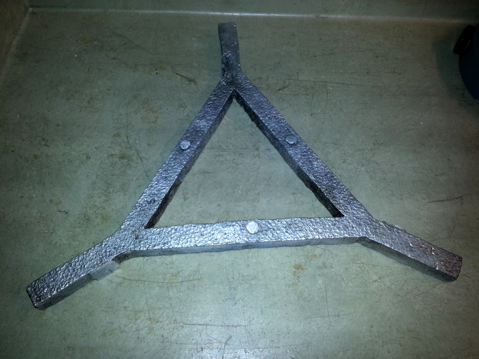 Here is a photo of the central support structure for the mirror cell after casting. You can see the texture of the foam in the finished casting. It is by far the largest thing I have made with
the lost-foam casting method. As you can see, it worked quite nicely.
Here is a photo of the central support structure for the mirror cell after casting. You can see the texture of the foam in the finished casting. It is by far the largest thing I have made with
the lost-foam casting method. As you can see, it worked quite nicely.
A piece like this could also easily be cut from aluminum plate or welded up from pieces of aluminum bar stock. There is no need to go to the trouble of casting it. I was already doing casting, so that's
just the way I made it.
 Here is a photo of the completed aluminum cell on the completed mirror. It is a spring loaded, push-pull design. The outer ring was cut from an aluminum plate. I considered trying to cast it
from aluminum too, but had a perfect aluminum plate on hand for the job. Here you can see how the pins fit into the sockets and the felt pads rest on the support points of the mirror.
Here is a photo of the completed aluminum cell on the completed mirror. It is a spring loaded, push-pull design. The outer ring was cut from an aluminum plate. I considered trying to cast it
from aluminum too, but had a perfect aluminum plate on hand for the job. Here you can see how the pins fit into the sockets and the felt pads rest on the support points of the mirror.
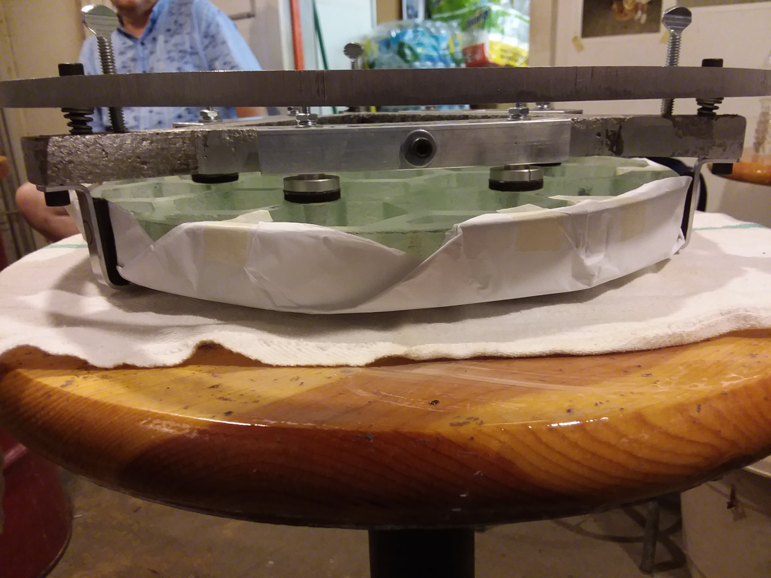 Here is another photo of the completed cell and mirror together. This photo better shows the springs and the push-pull bolts. The mirror is wrapped in tissue paper to protect the surface because
it has been aluminized.
Here is another photo of the completed cell and mirror together. This photo better shows the springs and the push-pull bolts. The mirror is wrapped in tissue paper to protect the surface because
it has been aluminized.
|
Click to learn how
to meet them
|
 Ok, finally. After years of work on the design and fabrication of the mirror and mirror cell, it was time to start building a scope for it. But what to to build? Another boring fast Newtonian?
I already have several of those. They are too commonplace already. I had gotten back into astrophotography big time the last few years. So I got to thinking why not build a dedicated
astrograph for photography only? The more I thought about it, the better the idea sounded. Especially after I acquired a used Losmandy G-11 mount with a 50lb payload capacity. I was pretty sure
I could build a 12.5 inch astrograph using this light-weight mirror technology and keep it well under the 50lb payload limit.
Ok, finally. After years of work on the design and fabrication of the mirror and mirror cell, it was time to start building a scope for it. But what to to build? Another boring fast Newtonian?
I already have several of those. They are too commonplace already. I had gotten back into astrophotography big time the last few years. So I got to thinking why not build a dedicated
astrograph for photography only? The more I thought about it, the better the idea sounded. Especially after I acquired a used Losmandy G-11 mount with a 50lb payload capacity. I was pretty sure
I could build a 12.5 inch astrograph using this light-weight mirror technology and keep it well under the 50lb payload limit.
Once I decided to build an astrograph, I knew a lot of the usual amateur big scope construction techniques weren't going to work. Since this was going to be a dedicated photographic instrument,
it was going to have to be rigid and rock-solid. Instruments used for visual observing can be quite sloppy in their construction because the eye is limited in what it can see. The camera though
is not at all forgiving. Any sagging, decentering, colimation shift or focus drift was going to show up and ruin the photos. So there would be no cardboard, wood or plastic used in the
construction of this astrograph. It was going to be robustly made totally from metal, mostly aluminum.
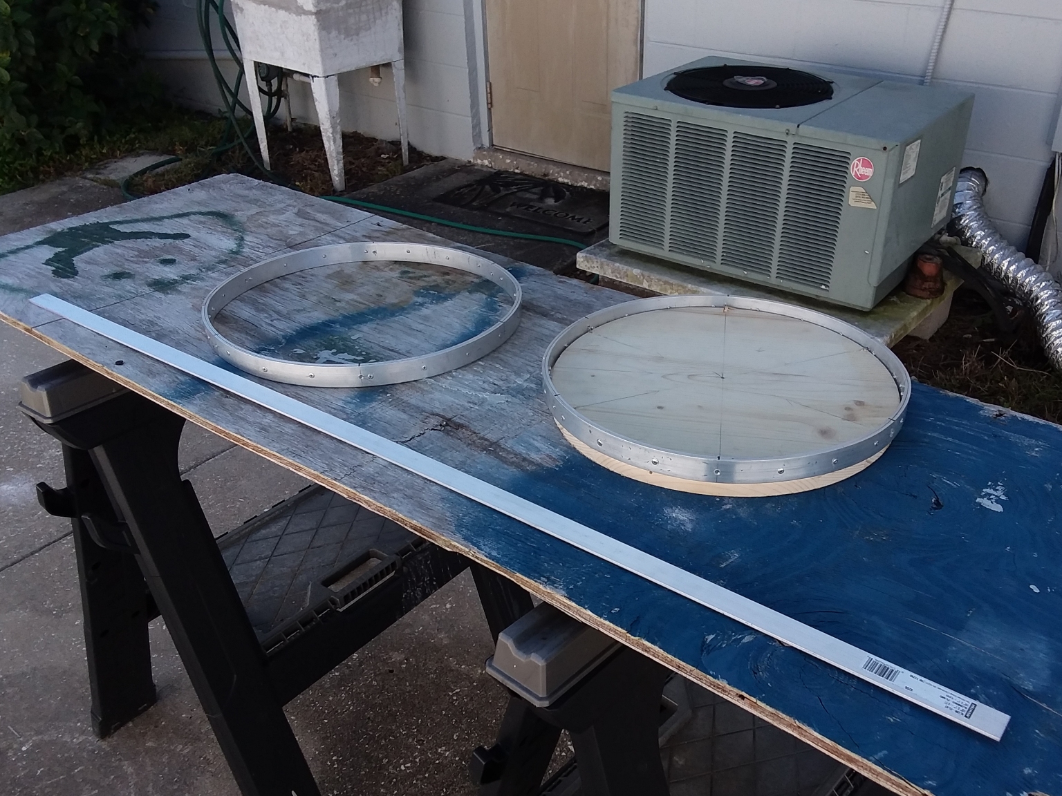
Here I am making the two aluminum rings the astrograph needed. I couldn't find a ring roller that that could do the job at a price I wanted to pay for what might be a one-time project. So I
came up with another way to make the rings.
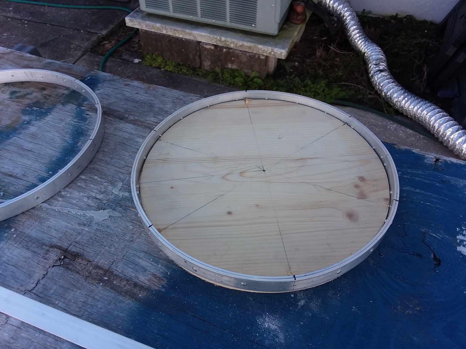 Here is a photo of one of the rings under construction. I made a round wooden disk with an outer diameter the same as the inner diameter of the rings I wanted to make. Then I bent two layers of
1/8 inch thick by 1 inch wide aluminum strips around the wood wheel, clamping them in place with long clamps (not shown). Then I drilled holes through both layers and riveted them together.
There was a whole lot of drill, debur, rivet and repeat to make the two rings. In the end though, they turned out pretty nice, and it was cheap and relatively easy to make them.
Here is a photo of one of the rings under construction. I made a round wooden disk with an outer diameter the same as the inner diameter of the rings I wanted to make. Then I bent two layers of
1/8 inch thick by 1 inch wide aluminum strips around the wood wheel, clamping them in place with long clamps (not shown). Then I drilled holes through both layers and riveted them together.
There was a whole lot of drill, debur, rivet and repeat to make the two rings. In the end though, they turned out pretty nice, and it was cheap and relatively easy to make them.
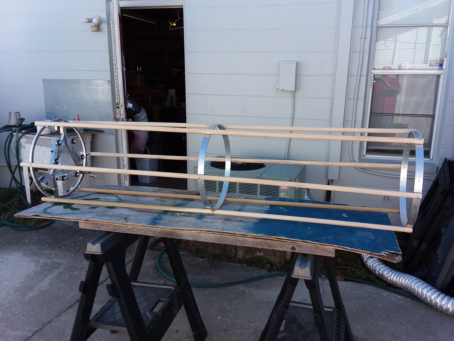 Once I had the mirror cell and two rings made, I could mock up the structure using wooden poles. The aluminum poles I ordered took a while to arrive, so the wooden stand-in poles were used
for much of the construction.
Once I had the mirror cell and two rings made, I could mock up the structure using wooden poles. The aluminum poles I ordered took a while to arrive, so the wooden stand-in poles were used
for much of the construction.
 Here I have started installing the diagonal strips while still using the wooden mockup poles.
To make the structure as rigid as possible, there need to be a lot of triangles in it. Triangles don't bend. They make a structure rigid. So I added a lot of aluminum strip diagonals that
criss-cross. Later I riveted the diagonals at the point where they cross to create triangles. This resulted in a remarkably rigid structure that does not sag, droop, bend or twist unless
a truly excessive amount of force is applied. See later photos for a better idea of how the diagonals are installed.
Here I have started installing the diagonal strips while still using the wooden mockup poles.
To make the structure as rigid as possible, there need to be a lot of triangles in it. Triangles don't bend. They make a structure rigid. So I added a lot of aluminum strip diagonals that
criss-cross. Later I riveted the diagonals at the point where they cross to create triangles. This resulted in a remarkably rigid structure that does not sag, droop, bend or twist unless
a truly excessive amount of force is applied. See later photos for a better idea of how the diagonals are installed.
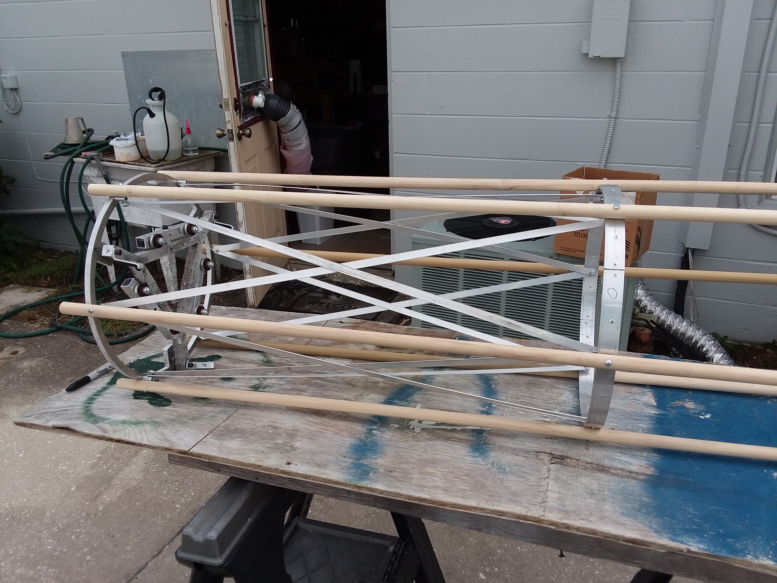
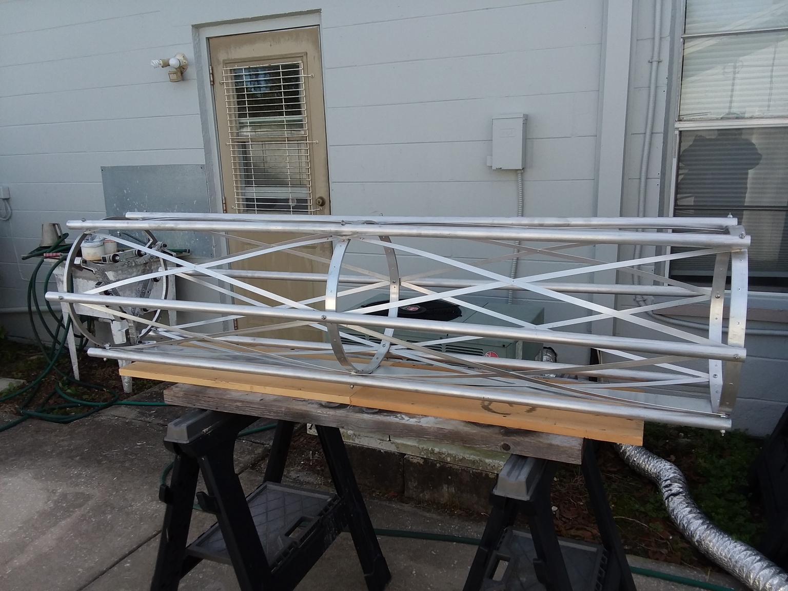 This photo shows the completed structure with all the diagonals installed and riveted at their crossing points. The aluminum rods I ordered had finally arrived. They have been cut to length,
drilled and installed in place of the wood rods used for mock up. The rods are one inch in diameter.
This photo shows the completed structure with all the diagonals installed and riveted at their crossing points. The aluminum rods I ordered had finally arrived. They have been cut to length,
drilled and installed in place of the wood rods used for mock up. The rods are one inch in diameter.
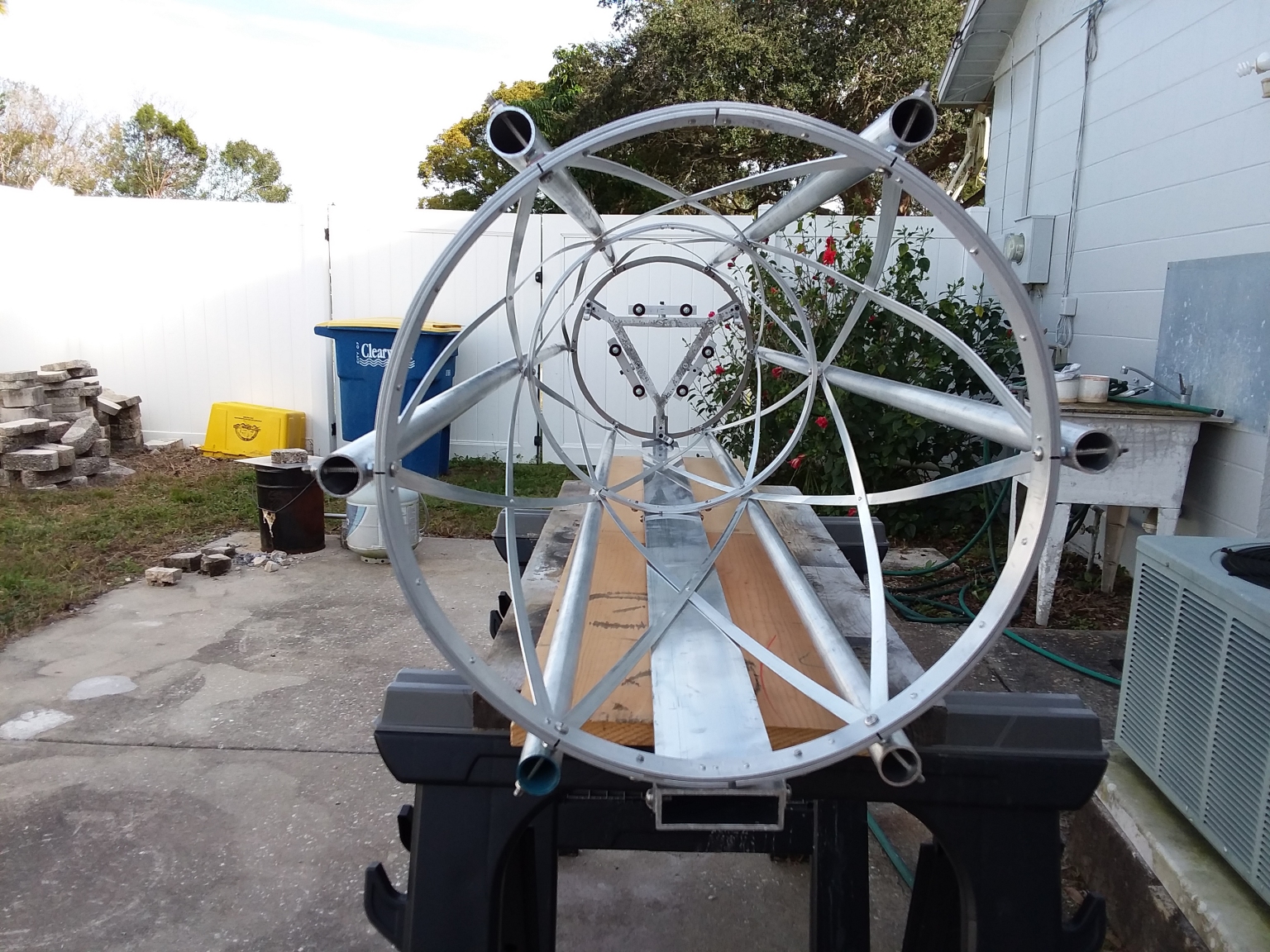 Here is a look down the front of the completed scope structure to the the mirror cell all the way at the back. Lots of triangles and lovely graceful curves. I wasn't expecting it to look quite
as pretty as it does. Bonus.
Here is a look down the front of the completed scope structure to the the mirror cell all the way at the back. Lots of triangles and lovely graceful curves. I wasn't expecting it to look quite
as pretty as it does. Bonus.
This photo also shows the heavy aluminum beam the entire structure is bolted to. The beam adds even more rigidity to the structure, and provides a mounting point for the attaching the
scope to the German Equatorial mount (see below).
 Next I needed a spider. It was going to need to be more robust than the usual DOB spider that just needs to support a diagonal mirror. This spider was going to have to support a
moto-focus focuser and a camera. I also wanted to be able to slide the spider forward or back along the optical tube to be able to accommodate different instruments and accessories
that need different amounts of back focus. After giving it a lot of thought I came up with something that works quite well.
Next I needed a spider. It was going to need to be more robust than the usual DOB spider that just needs to support a diagonal mirror. This spider was going to have to support a
moto-focus focuser and a camera. I also wanted to be able to slide the spider forward or back along the optical tube to be able to accommodate different instruments and accessories
that need different amounts of back focus. After giving it a lot of thought I came up with something that works quite well.
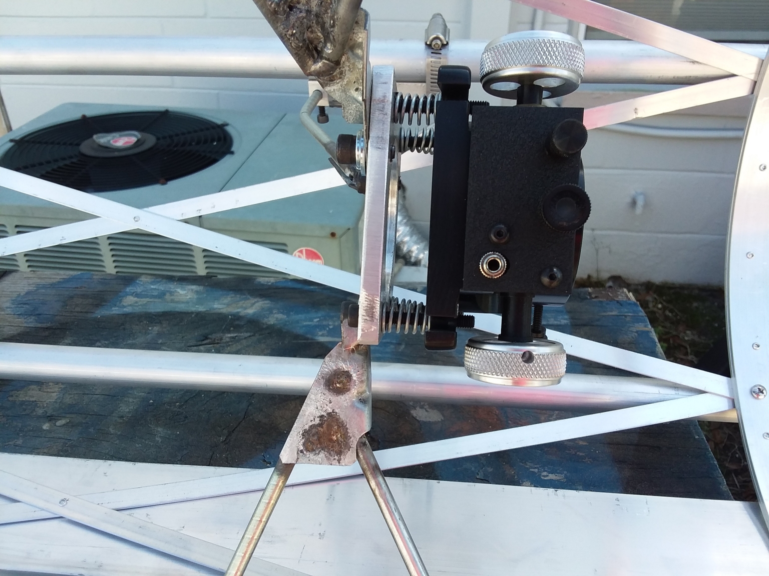
 The spider vanes are each made from two parallel lengths of ¼ inch steel rod that bend at their ends to almost touch. These are then welded to steel support brackets cut from roofing
hurricane clips I found in the hardware store. Excess metal was trimmed from the hurricane clips and a mounting hole was drilled. After totally fabricating the spider vanes from scratch,
I saw some U-clamps in the hardware store that would have probably worked just as well and saved me a lot of fabrication time and effort.
The spider vanes are each made from two parallel lengths of ¼ inch steel rod that bend at their ends to almost touch. These are then welded to steel support brackets cut from roofing
hurricane clips I found in the hardware store. Excess metal was trimmed from the hurricane clips and a mounting hole was drilled. After totally fabricating the spider vanes from scratch,
I saw some U-clamps in the hardware store that would have probably worked just as well and saved me a lot of fabrication time and effort.
I made a square plate from aluminum with a 2.5 inch diameter hole in the middle that the spider vanes bolt to and the motofocus unit will mount to via springs and bolts to adjust tilt.
The ends of the spider vanes bolt into threaded holes in the plate.
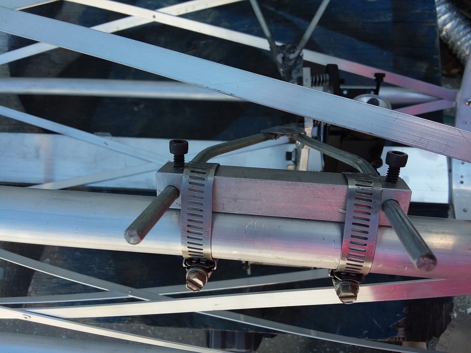 To support the vanes I cut some four inch lengths of square aluminum tubing. Each was drilled near the ends for passage holes for the spider vane rods, and an intersecting set screw
hole was drilled and tapped. The vane rods can be moved in or out for centering, then locked in place with the set screws.
To support the vanes I cut some four inch lengths of square aluminum tubing. Each was drilled near the ends for passage holes for the spider vane rods, and an intersecting set screw
hole was drilled and tapped. The vane rods can be moved in or out for centering, then locked in place with the set screws.
I was originally going to attach these square rods to sliding rings that would move easily up and down the aluminum tubes and lock in place with set screws. After temporarily assembling
the spider by just clamping the rods to the tubes with hose clamps, I found that worked well enough to not bother with the sliding rings. The spider assembly probably won’t get moved
often enough to justify the extra effort of making and installing them.
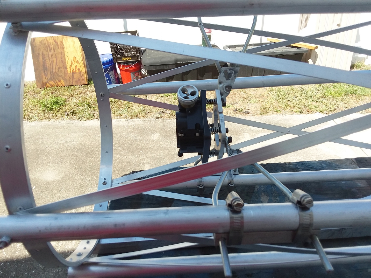
 I already had an old moto-focus unit on hand for a Newtonian type scope. The square profile and wide base is not ideal for placing in the light path of the scope. A round base made
for refractor use would probably be better. However, I wanted to see how well this scope worked before sinking the money into it for a new moto-focus. Besides, I was planning on
using one of my Nikon SLR cameras as the imager in the beginning, and it is even wider than the moto-focus base. The camera body blocks a lot of light, but again I didn’t want to
sink a lot of money into this project for a dedicated (round and slim) astro camera until I knew if it was all going to work. Upgrading the focuser and camera are always possible
in the future. It’s on my to-do list now since Al seems to be showing a lot of potential.
I already had an old moto-focus unit on hand for a Newtonian type scope. The square profile and wide base is not ideal for placing in the light path of the scope. A round base made
for refractor use would probably be better. However, I wanted to see how well this scope worked before sinking the money into it for a new moto-focus. Besides, I was planning on
using one of my Nikon SLR cameras as the imager in the beginning, and it is even wider than the moto-focus base. The camera body blocks a lot of light, but again I didn’t want to
sink a lot of money into this project for a dedicated (round and slim) astro camera until I knew if it was all going to work. Upgrading the focuser and camera are always possible
in the future. It’s on my to-do list now since Al seems to be showing a lot of potential.
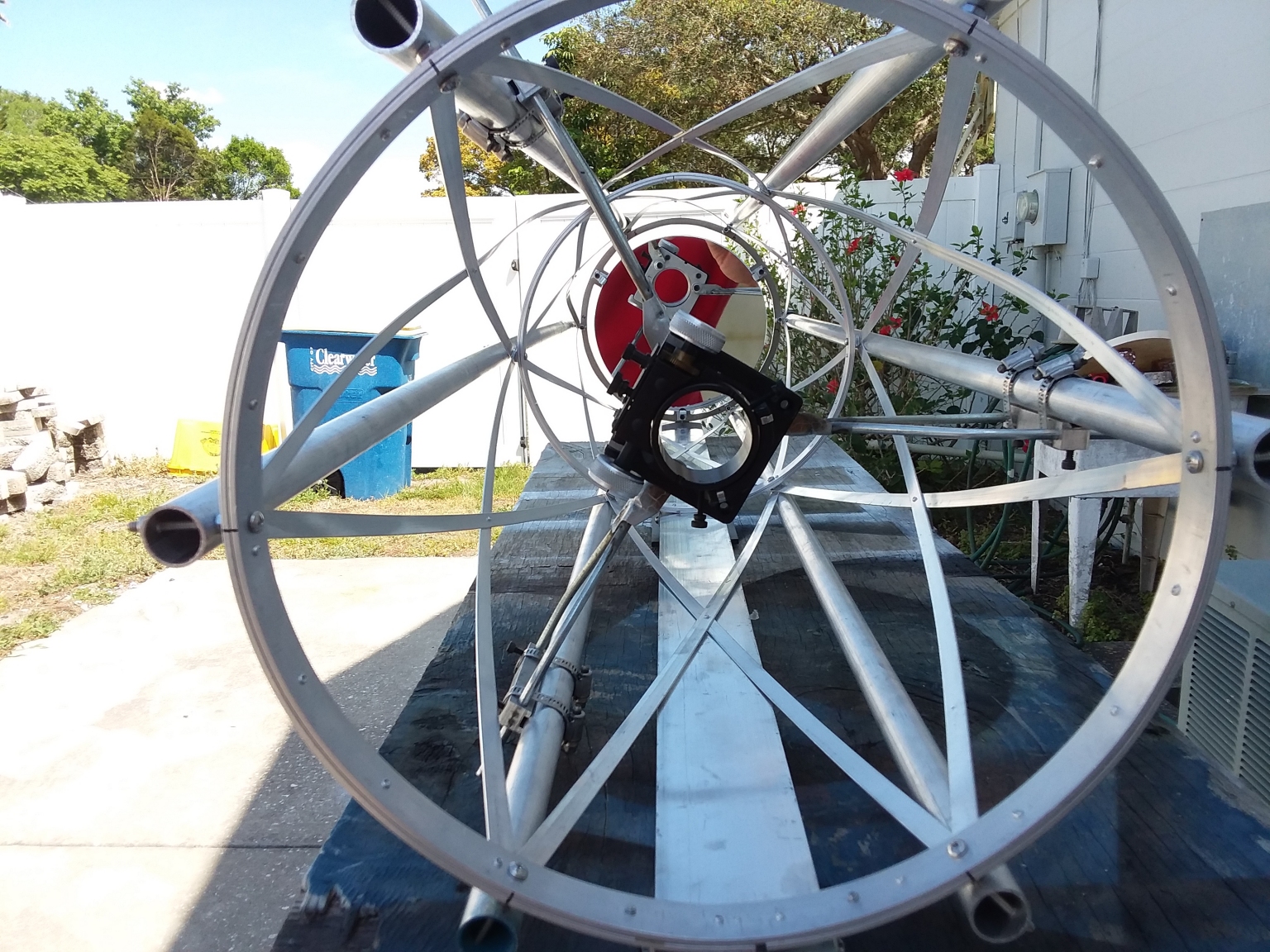
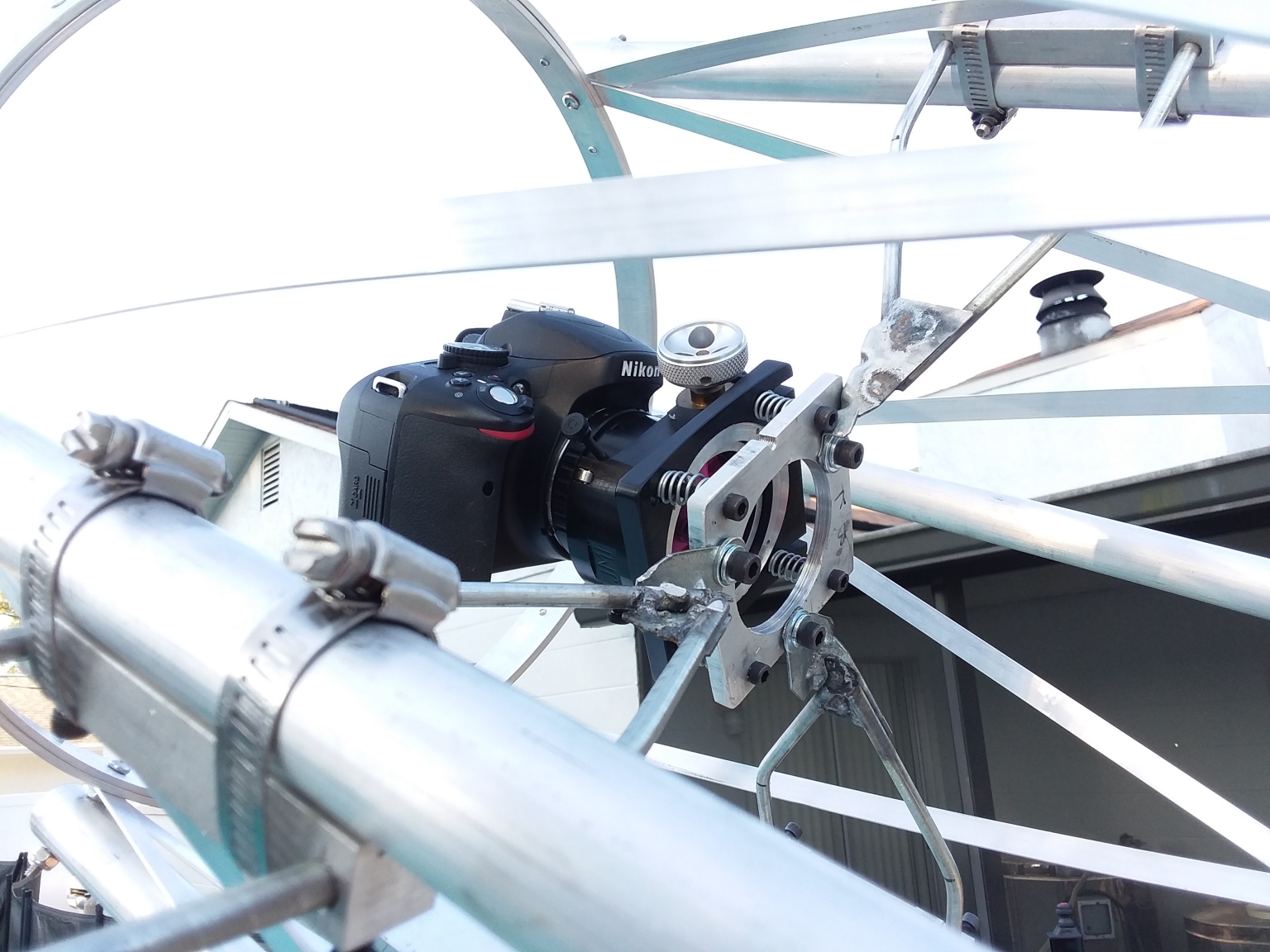 Here is a shot of the completed spider and focuser assembly with the Nikon camera installed. I am pleased with how easily adjustable everything is for centering and tilt. Collimation is a
breeze, and stays rock solid once everything is tightened down. Lots of parts still needed to be painted ultra flat black when this photo was taken.
Here is a shot of the completed spider and focuser assembly with the Nikon camera installed. I am pleased with how easily adjustable everything is for centering and tilt. Collimation is a
breeze, and stays rock solid once everything is tightened down. Lots of parts still needed to be painted ultra flat black when this photo was taken.
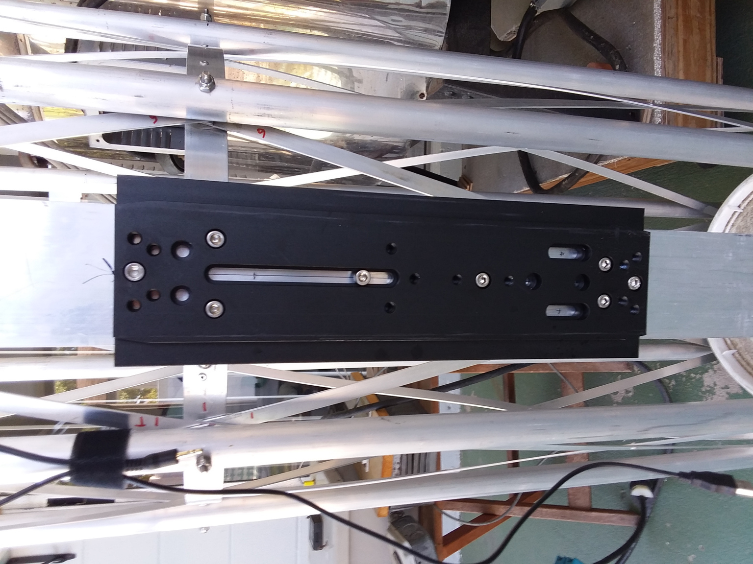 I found the balance point of the scope and mounted a Losmandy style dovetail plate on the main support beam, centered on that point. It is a long dovetail, so I can slide the scope
back and forth quite a bit on the mount to achieve perfect balance when different accessories are added or removed. Since the mirror is so light, the balance point is
surprisingly close to the center of the tube.
I found the balance point of the scope and mounted a Losmandy style dovetail plate on the main support beam, centered on that point. It is a long dovetail, so I can slide the scope
back and forth quite a bit on the mount to achieve perfect balance when different accessories are added or removed. Since the mirror is so light, the balance point is
surprisingly close to the center of the tube.
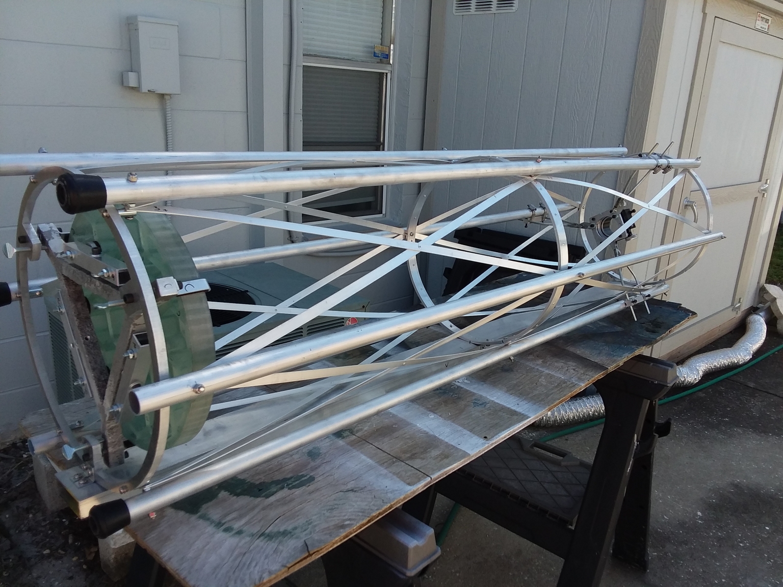
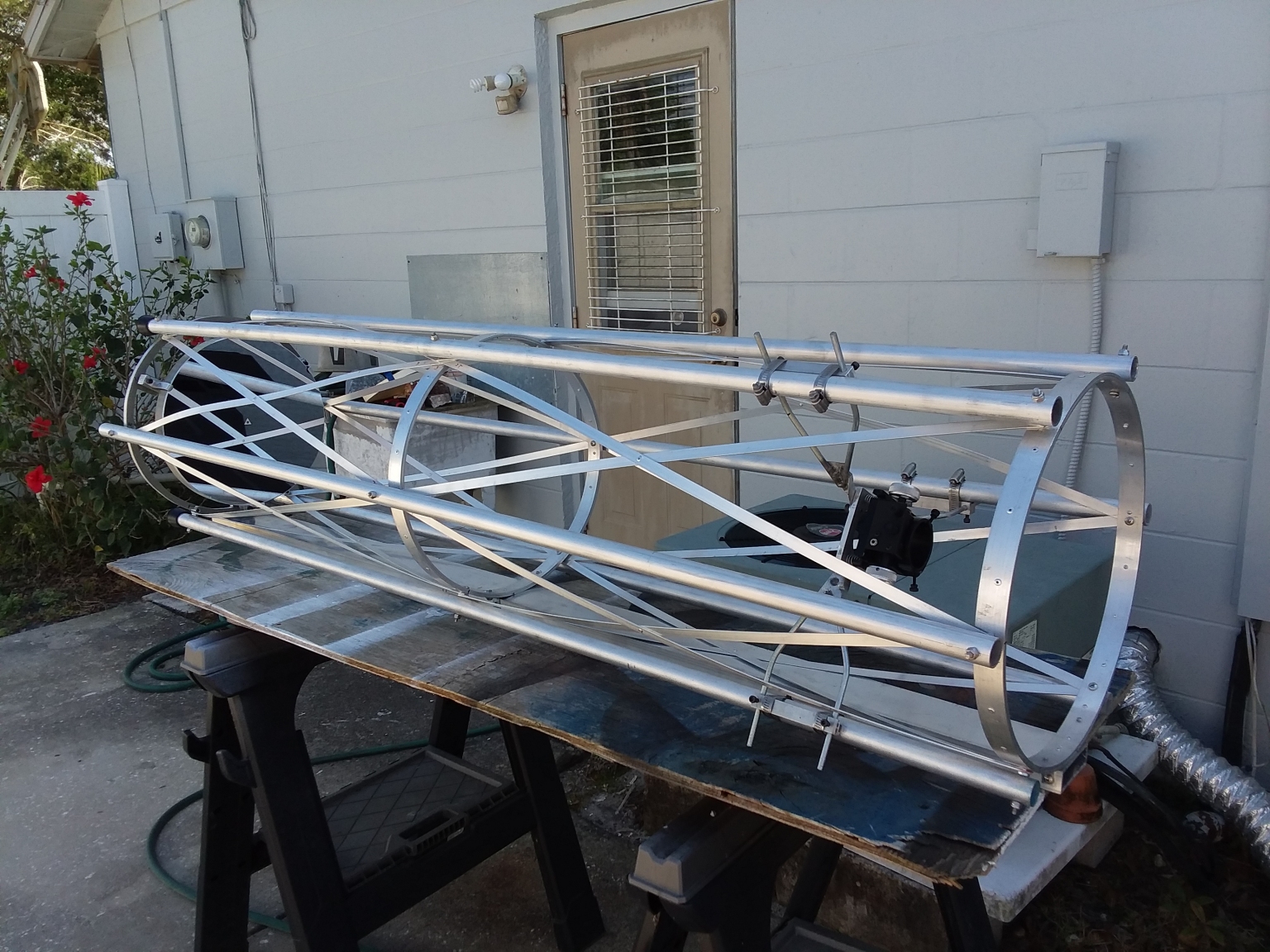 So here is a photo of the essentially completed astrograph. It still needs a few bells and whistles and smartening up, but it is mostly done. First light would happen shortly after this photo
was taken. The completed astrograph, with camera installed, only weighs a bit over 34 lbs. So I brought it in well under the payload capacity of my G-11 Mount, with room to spare even
after I hang a few accessories on it.
So here is a photo of the essentially completed astrograph. It still needs a few bells and whistles and smartening up, but it is mostly done. First light would happen shortly after this photo
was taken. The completed astrograph, with camera installed, only weighs a bit over 34 lbs. So I brought it in well under the payload capacity of my G-11 Mount, with room to spare even
after I hang a few accessories on it.
 Here is another view of the essentially completed astrograph from the rear with the mirror installed. Nothing has been painted black yet.
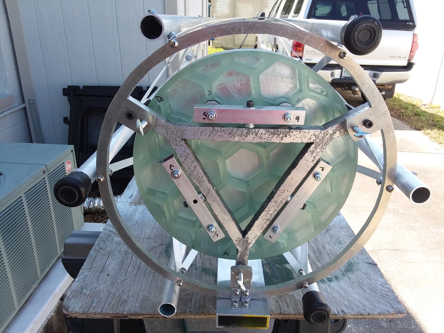 Here is a view showing the primary mirror cell and mirror. Damn, that is a good looking mirror if I do say so myself. There will eventually be a cooling fan installed behind the mirror cell to
keep the mirror at ambient temperature.
Here is a view showing the primary mirror cell and mirror. Damn, that is a good looking mirror if I do say so myself. There will eventually be a cooling fan installed behind the mirror cell to
keep the mirror at ambient temperature.
 Here is a close-up showing details of the primary mirror cell.
Here Al is finally mated to the Losmandy G-11 mount and ready for first light.
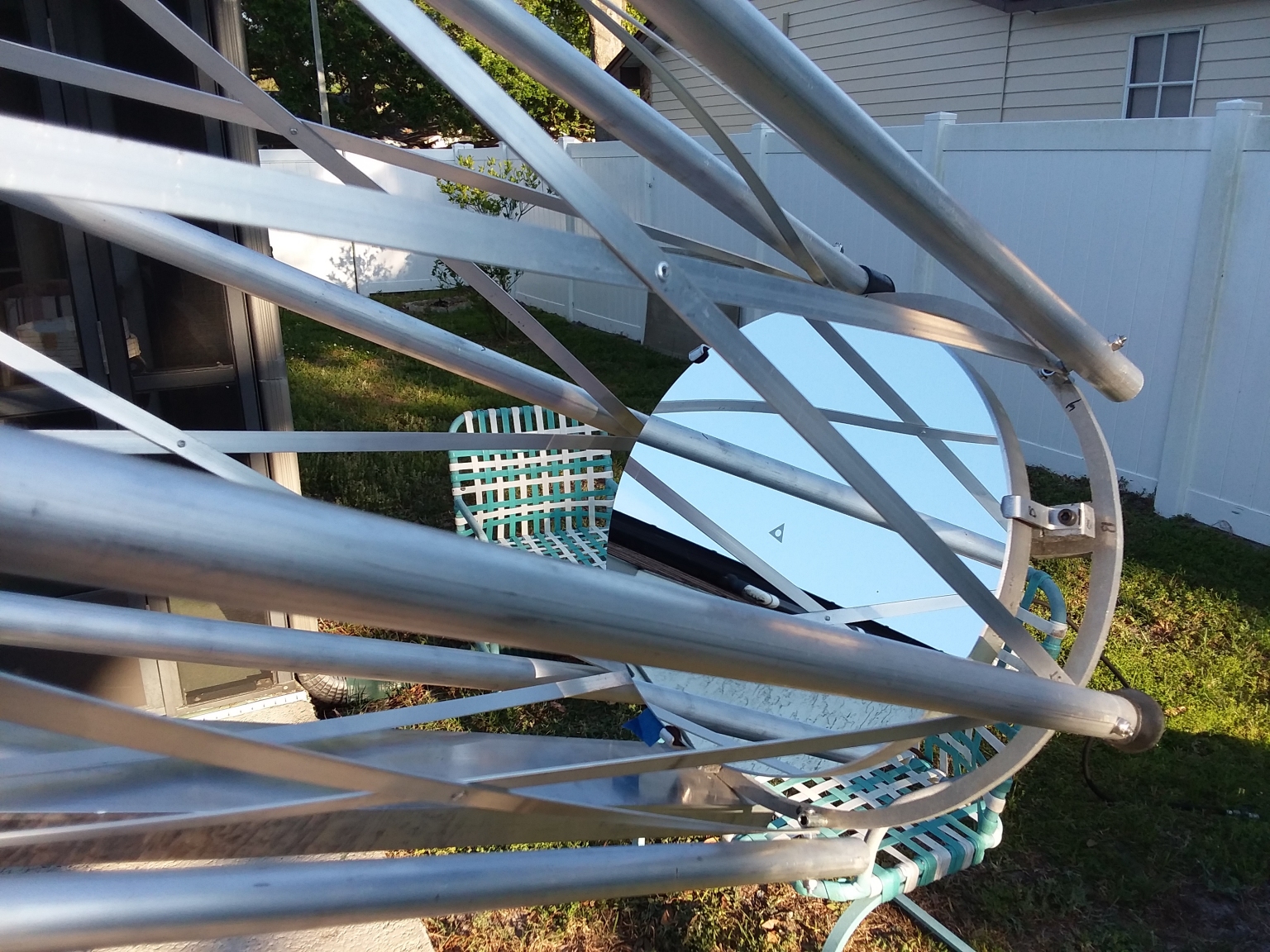 Here is another daylight view of Al's primary mirror showing the center marking used for collimation. To collimate Al I remove the camera from the focuser and insert a 2 inch to 1.25 inch
adapter. then I install my laser collimator. Collimation is amazingly easy and simple. I had already ensured the focuser was centered and locked down the centering adjustment screws. Next
I just adjusted the tilt screws on the spider to center the laser beam on the center marker. Then I adjust the push/pull bolts on the back of the primary to make the beam return to its
point of origin. All that is left is to lock down the lock bolts and replace the adapter and collimator with the camera. Collimation only takes a couple of minutes and is very easy. It
is also rock solid once done. I can remove the scope from the mount, move it around, and put it back on with only minimal collimation drift. Collimation is so easy though that I always check it
and tweak it to perfection before each use.
Here is another daylight view of Al's primary mirror showing the center marking used for collimation. To collimate Al I remove the camera from the focuser and insert a 2 inch to 1.25 inch
adapter. then I install my laser collimator. Collimation is amazingly easy and simple. I had already ensured the focuser was centered and locked down the centering adjustment screws. Next
I just adjusted the tilt screws on the spider to center the laser beam on the center marker. Then I adjust the push/pull bolts on the back of the primary to make the beam return to its
point of origin. All that is left is to lock down the lock bolts and replace the adapter and collimator with the camera. Collimation only takes a couple of minutes and is very easy. It
is also rock solid once done. I can remove the scope from the mount, move it around, and put it back on with only minimal collimation drift. Collimation is so easy though that I always check it
and tweak it to perfection before each use.
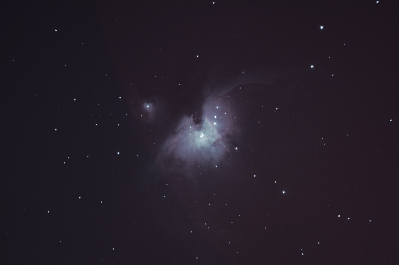 Here is the first light image from the astrograph which I was by now affectionately calling Al. Orion was fortuitously well placed that night, so it became Al's first target.
I was just blown away by how much light this instrument gathers and sends to the focal plane. My first few images were nearly totally saturated. At first I assumed it was due to stray light.
Eventually I figured out that AL was just gathering so much light that the images were horribly over-exposed. I started out using settings I was used to using with much smaller and optically
slower instruments. So I kept shortening the exposures and reducing the ISO setting on the camera
until I started getting shots that weren't totally over-exposed. This shot is a stack of five 15 second exposures shot at ISO 100! Amazing!
The stars are quite elongated, but that is due to a tracking problem with the mount, not a problem with the astrograph. My poor old Losmandy mount is in need of some TLC. That is coming in
the form of a total drive and electronics upgrade that will be done soon. Still, this is an amazing first light image. I couldn't be happier with it. Things are only going to get better. The
astrograph is going to have all parts in the light path painted ultra-flat black. A light shield shroud is going to be installed. The remote focus parts and Losmandy upgrade parts have just
arrived. A reflex sight and guidescope still need to be installed. This instrument is going to be a work in progress for quite a while until I get it tweaked to my satisfaction. Eventually
I will be taking it to the SPAC dark sky observing site to give it a real workout. Eventually though, to get the most out of this amazing instrument, it is going to need to be permanently
mounted and housed in an observatory. Building one is on my to-do list for my remote Arizona property.
|
Click to learn how
to meet them
|
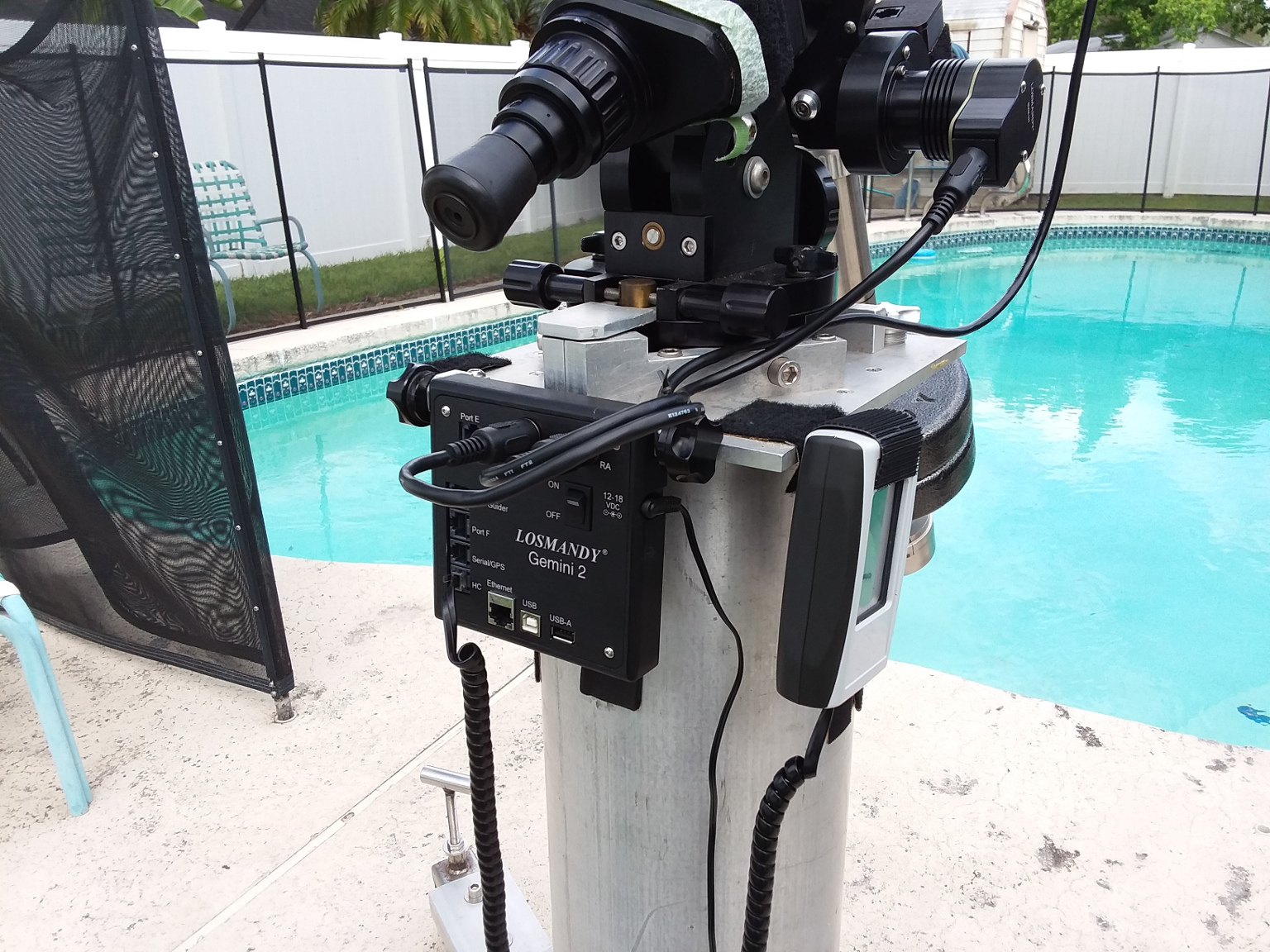 UPDATE: My Losmandy G-11 mount has had a complete motor and electronics upgrade. It is now operating on the latest Gemini II electronics with high-torque servo motors. The instructions
included with the upgrade kit were pretty minimal, but I managed to figure it all out and get everything working and setup.
UPDATE: My Losmandy G-11 mount has had a complete motor and electronics upgrade. It is now operating on the latest Gemini II electronics with high-torque servo motors. The instructions
included with the upgrade kit were pretty minimal, but I managed to figure it all out and get everything working and setup.
I've also painted some of the shiny aluminum parts of Al ultra flat black. I'm starting work on a light shroud to keep stray light out from the sides. I'm waiting for a clear weather window and
free time to give Al another test run.
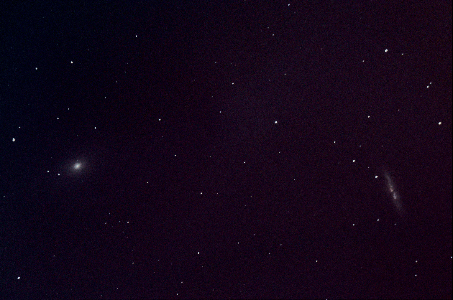 UPDATE: This is the second light photo of M81 and M82. The conditions were terrible. It was taken from my very light polluted urban back yard on a windy night. Some parts in the optical
path have been painted black since the previous photo, but there is still no shroud to block stray light. The red haze across the right side of the photo is likely stray light from a street light
about a block away in the general direction Al was pointing. I was also still having trouble with the remote focus. Even with all those problems, the potential of this instrument is showing
through. This is again a short stack of 15 second exposures at ISO 200. The galaxies were plainly visible in even the individual 15 second frames before stacking. Al gathers a lot of light.
UPDATE: This is the second light photo of M81 and M82. The conditions were terrible. It was taken from my very light polluted urban back yard on a windy night. Some parts in the optical
path have been painted black since the previous photo, but there is still no shroud to block stray light. The red haze across the right side of the photo is likely stray light from a street light
about a block away in the general direction Al was pointing. I was also still having trouble with the remote focus. Even with all those problems, the potential of this instrument is showing
through. This is again a short stack of 15 second exposures at ISO 200. The galaxies were plainly visible in even the individual 15 second frames before stacking. Al gathers a lot of light.
Once I was done with the imaging tests, I tried to get the focus better. I finally achieved probably the best possible focus before wrapping it up for the night. At focus coma becomes the main
issue with the images. AL is going to need a coma corrector to get the most out of him.
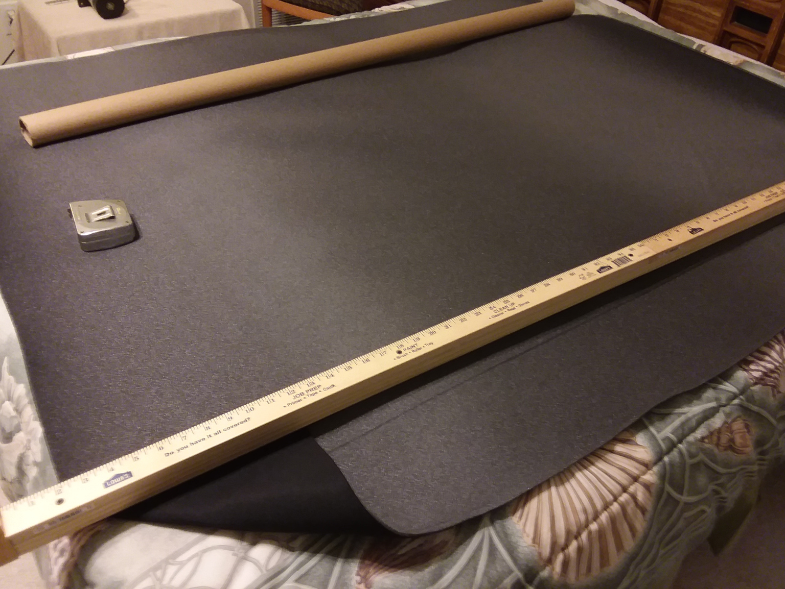 UPDATE: There is simply no point in doing any further testing on Al until I get a proper light shroud made and installed to keep stray light out of the optical path. I plan on installing it
inside the aluminum lattice work. That way I won't have to bother painting all of Al's lovely, shiny aluminum bits. I found some fabric that may work. It is actually not so much fabric as a thin sheet
of foam with very black cloth on one side. It is normally used for car headliners. It is amazingly light and relatively inexpensive. I bought enough to make the shroud and began cutting it to
size and slitting it where it would need to go around the spider vanes. The only work surface I had that was large enough for the job was my queen-size bed. The next time Al goes under the stars
he will have a light shroud installed.
UPDATE: There is simply no point in doing any further testing on Al until I get a proper light shroud made and installed to keep stray light out of the optical path. I plan on installing it
inside the aluminum lattice work. That way I won't have to bother painting all of Al's lovely, shiny aluminum bits. I found some fabric that may work. It is actually not so much fabric as a thin sheet
of foam with very black cloth on one side. It is normally used for car headliners. It is amazingly light and relatively inexpensive. I bought enough to make the shroud and began cutting it to
size and slitting it where it would need to go around the spider vanes. The only work surface I had that was large enough for the job was my queen-size bed. The next time Al goes under the stars
he will have a light shroud installed.
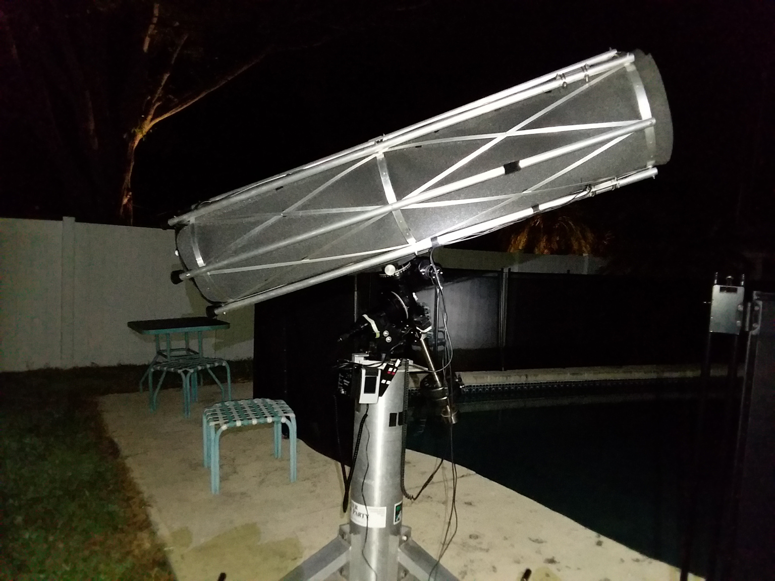 UPDATE: Here is a photo of Al from a couple of nights ago. The stray light blocking shroud has been installed. It's still a work in progress and needs some more neatening up, but it was
time to test and see how much better Al could do without stray light interfering. This would be a good test. Not only did I have all the usual stray light sources in my neighborhood to deal with,
but there was also a nearly half full moon shining down too.
UPDATE: Here is a photo of Al from a couple of nights ago. The stray light blocking shroud has been installed. It's still a work in progress and needs some more neatening up, but it was
time to test and see how much better Al could do without stray light interfering. This would be a good test. Not only did I have all the usual stray light sources in my neighborhood to deal with,
but there was also a nearly half full moon shining down too.
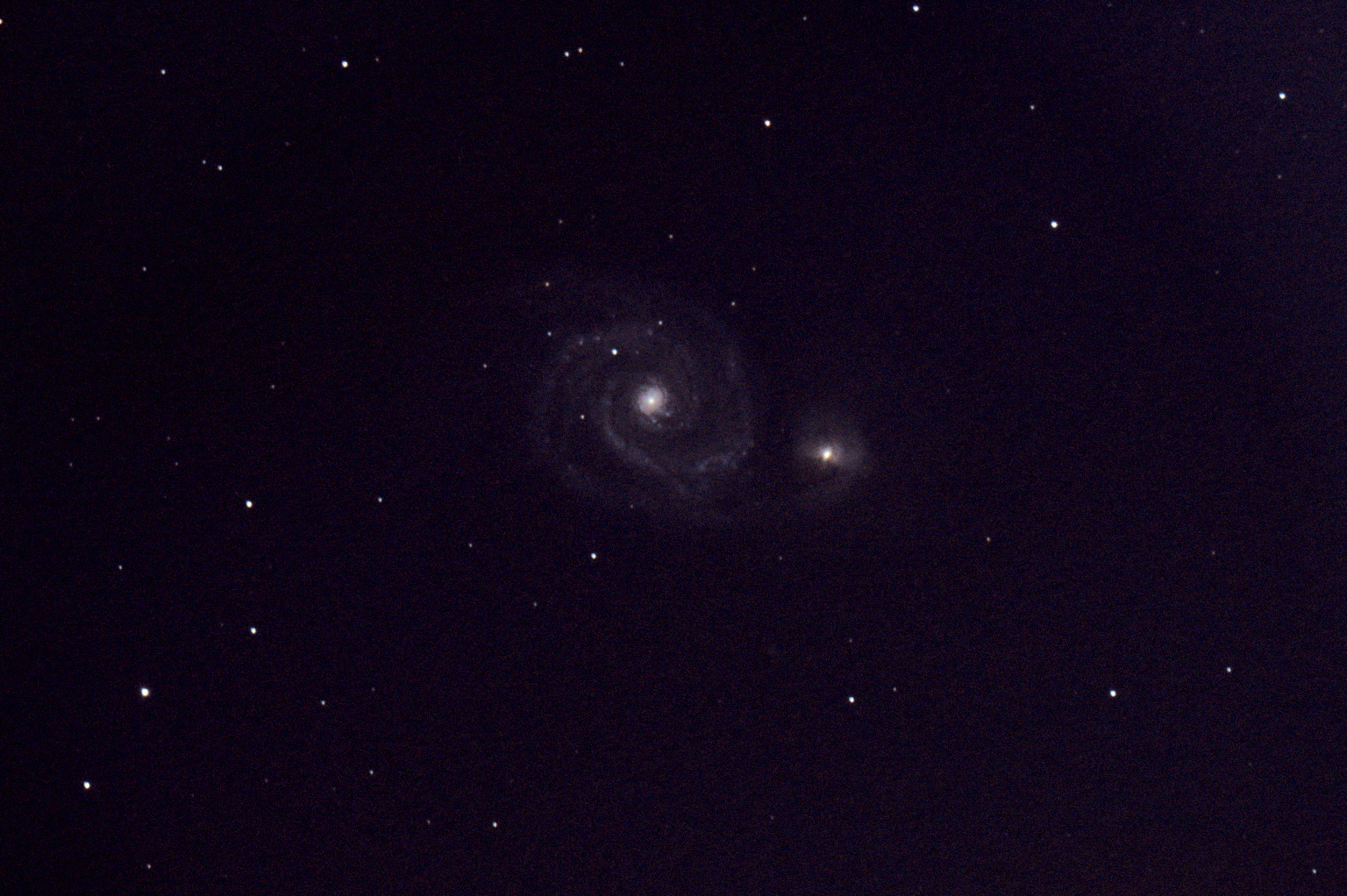 So here is a photo of M51 taken with the shroud in place. I think it is a vast improvement as far as the stray light issues go. The sky was pretty piss-poor for deep sky photography though.
Between the light pollution and the moonlight, the sky was pretty bright and deep sky objects were pretty washed out. I had to really stretch the contrast to bring out the details in this
photo. That made it kind of grainy and blotchy. Only two of the half dozen objects I tried to image came out half way decent. On the bright side, Al now has a coma corrector. Plus I am
getting a handle on focusing. So things are improving slowly. I'll try again the next clear and moonless night. Someday I need to truck Al and the Losmandy mount out into the boonies
away from the city lights and see what he can really do.
So here is a photo of M51 taken with the shroud in place. I think it is a vast improvement as far as the stray light issues go. The sky was pretty piss-poor for deep sky photography though.
Between the light pollution and the moonlight, the sky was pretty bright and deep sky objects were pretty washed out. I had to really stretch the contrast to bring out the details in this
photo. That made it kind of grainy and blotchy. Only two of the half dozen objects I tried to image came out half way decent. On the bright side, Al now has a coma corrector. Plus I am
getting a handle on focusing. So things are improving slowly. I'll try again the next clear and moonless night. Someday I need to truck Al and the Losmandy mount out into the boonies
away from the city lights and see what he can really do.
a lady to
learn how
to meet her