It can get hot in my cabin on my remote Arizona property. I normally only spend time there in the Spring and Fall, but there can still be some pretty hot
days. I have plenty of power, thanks to my solar panels and
home-built wind turbine.
So I decided to build a small swamp cooler to keep the cabin cool. It was a
pretty quick and easy build. This web site shows how I did it.
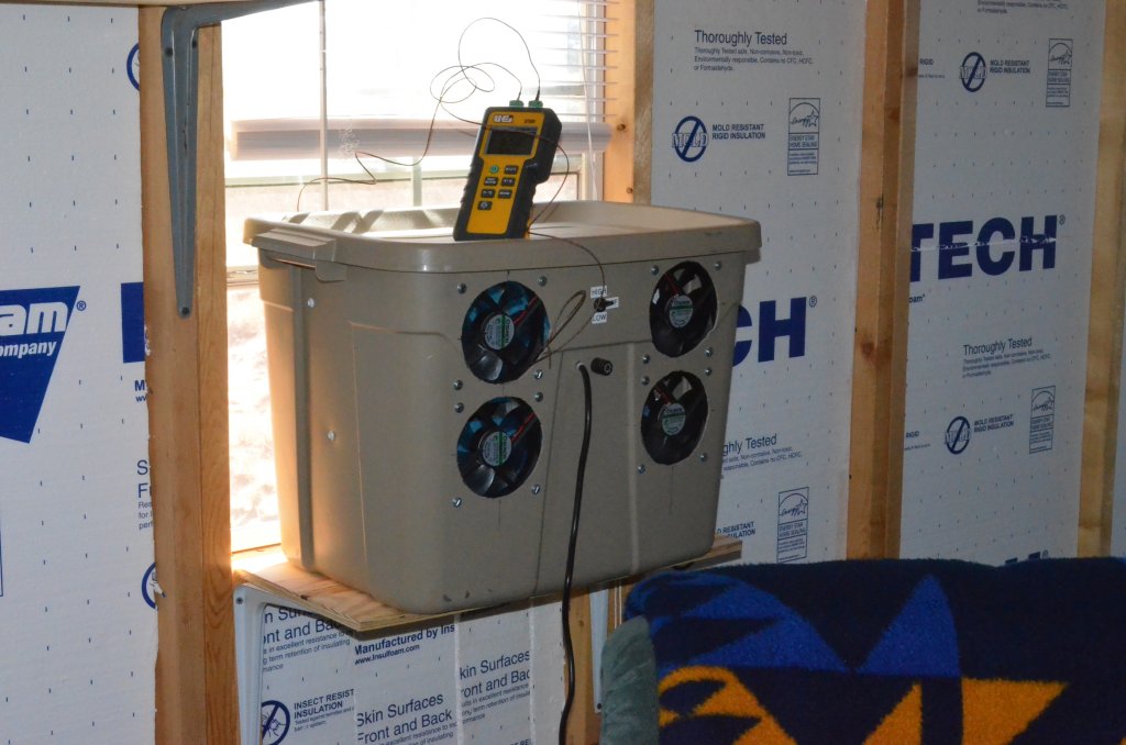
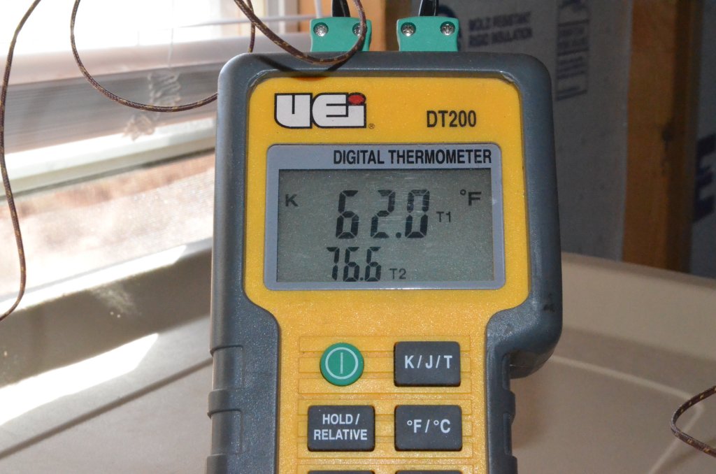
This photo shows the completed unit on a shelf I built in front of one of the cabin windows. It is drawing in hot, dry outside air and blowing out cool,
moist air into the cabin. On top is a digital thermometer unit measuring the temperature difference between the air going in and the air coming out.
The thermometer is not needed for normal operation and is just being used for testing purposes. In this test I was seeing a 14 degree F temperature difference
between incoming and outgoing air. See photo near the bottom of the page.
Click on any of the photos for a larger and more detailed view.
 Some of you are probably asking "What in the world is a swamp cooler?" And you people asking that probably live in cool or humid climates. Everyone who
lives in the hot and dry Southwest knows what they are. Swamp coolers are simple evaporative coolers. They cool air by taking advantage of the fact that
evaporating water cools its surroundings. Swamp coolers only work well in arid climates where the relative humidity is low, temperatures are high, and getting water to
evaporate is dead easy. They don't work well in humid climates, so actual air conditioning is required for cooling in those places. In my area of Arizona where the
humidity tends to hover around 5% on hot days, swamp coolers work great, and most houses use them instead of air conditioning. Large units can cool
large homes in even the worst desert heat, and provide the added benefit of humidifying the inside air. I am going to be building a small, portable
unit to cool a small cabin.
Some of you are probably asking "What in the world is a swamp cooler?" And you people asking that probably live in cool or humid climates. Everyone who
lives in the hot and dry Southwest knows what they are. Swamp coolers are simple evaporative coolers. They cool air by taking advantage of the fact that
evaporating water cools its surroundings. Swamp coolers only work well in arid climates where the relative humidity is low, temperatures are high, and getting water to
evaporate is dead easy. They don't work well in humid climates, so actual air conditioning is required for cooling in those places. In my area of Arizona where the
humidity tends to hover around 5% on hot days, swamp coolers work great, and most houses use them instead of air conditioning. Large units can cool
large homes in even the worst desert heat, and provide the added benefit of humidifying the inside air. I am going to be building a small, portable
unit to cool a small cabin.
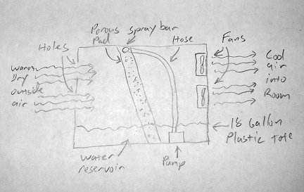
The principal is simple. A porous pad is kept moist with water fed by a pump. The water is pumped out of a reservoir at the bottom of the unit, to the top of the
pad. It trickles down through the pad to keep it moist. Fans blow warm, dry air through the moist pad. As the air passes through the porous pad, water evaporates
and cools the air. Cool moist air is exhausted into the living space. Larger units are connected to the domestic water supply via a float valve to keep
the reservoir full. My little unit will just need to be refilled manually from time to time. I used fans and a pump that can run on 12V DC. That way
my solar and wind systems can power it.
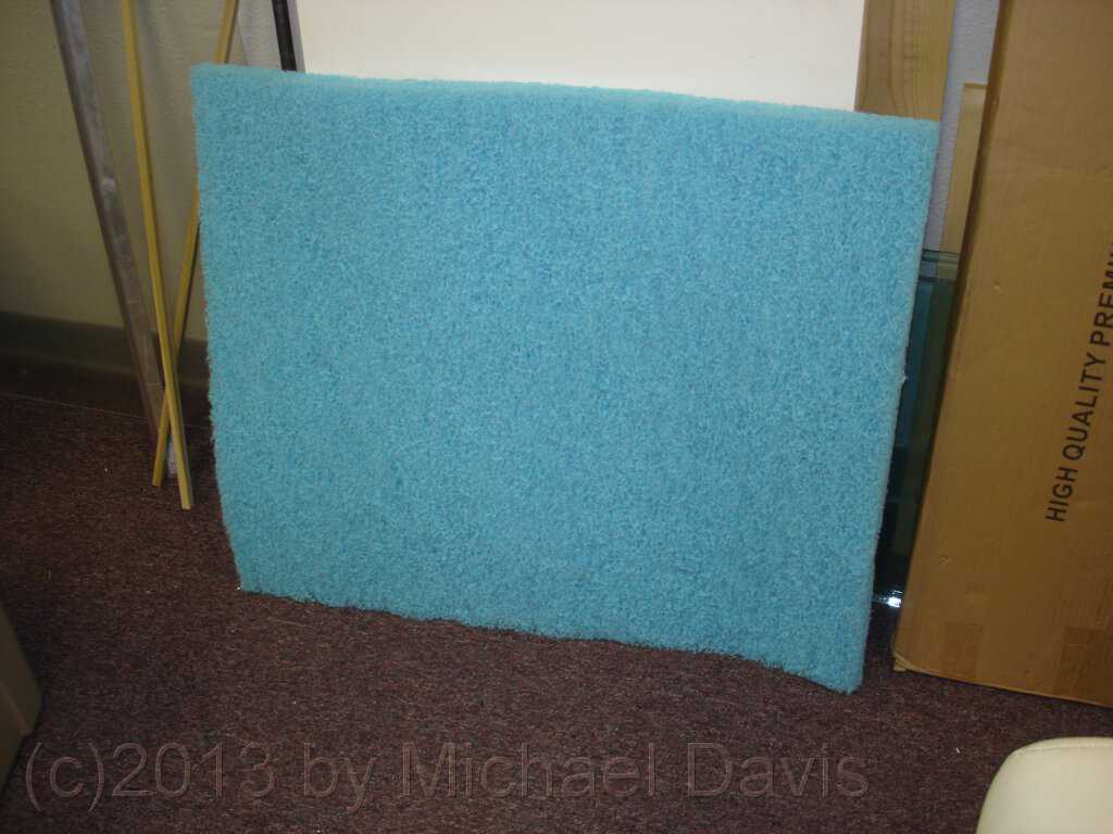
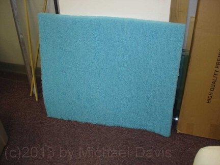 I started by buying the porous pad. These can be found in any hardware or homecenter store in areas where swamp coolers are in widespread use. They come in
a variety of sizes and materials, and are quite inexpensive. I opted for this blue, plastic sponge pad.
I started by buying the porous pad. These can be found in any hardware or homecenter store in areas where swamp coolers are in widespread use. They come in
a variety of sizes and materials, and are quite inexpensive. I opted for this blue, plastic sponge pad.
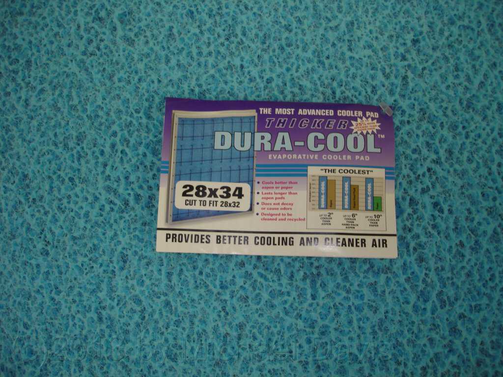
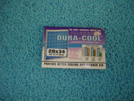 Here is a close-up of the pad showing the label. The pad is inexpensive. It was made for a large house-size swamp cooler. I will cut a piece out of it
for my small unit and have enough left over for at least one more replacement pad if needed.
Here is a close-up of the pad showing the label. The pad is inexpensive. It was made for a large house-size swamp cooler. I will cut a piece out of it
for my small unit and have enough left over for at least one more replacement pad if needed.
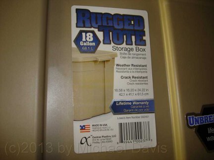 My cabin is small. I figured that only a fairly small swamp cooler would be needed to lower the temperature inside the cabin to something comfortable during
the hottest part of the day. I wanted to build one that would sit on an extended window sill and pull in outside air and cool it before exhausting it into
the cabin. So I decided to build a small swamp cooler using an 18 gallon plastic tote. It is just about the perfect size, and they are dirt cheep too.
My cabin is small. I figured that only a fairly small swamp cooler would be needed to lower the temperature inside the cabin to something comfortable during
the hottest part of the day. I wanted to build one that would sit on an extended window sill and pull in outside air and cool it before exhausting it into
the cabin. So I decided to build a small swamp cooler using an 18 gallon plastic tote. It is just about the perfect size, and they are dirt cheep too.
 Challenge Accepted!
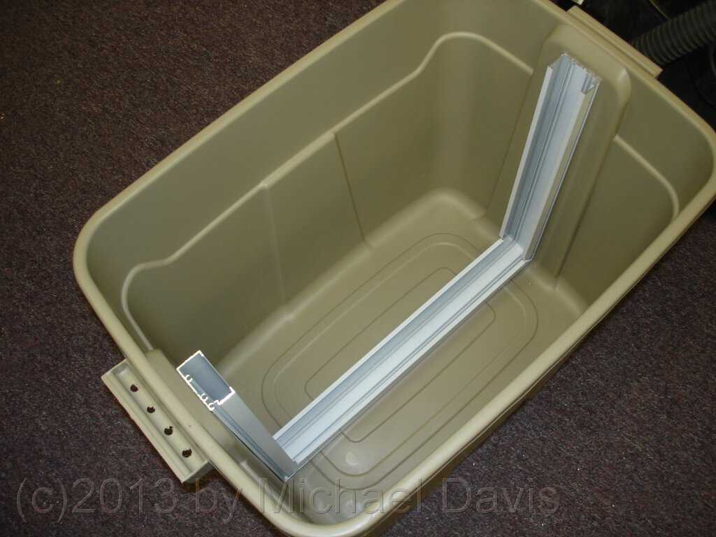
 I began the construction by locating a piece of aluminum U channel that is wide enough inside to accommodate the thickness of the pad. I measured
the inside dimensions of the tote and cut a piece of the channel to the length of the bottom plus the height X 2. Then I cut relief cuts in the
sides of the channel and bent it into a big U-shaped frame to old the pad. In this photo I am test-fitting the frame in the tote.
I began the construction by locating a piece of aluminum U channel that is wide enough inside to accommodate the thickness of the pad. I measured
the inside dimensions of the tote and cut a piece of the channel to the length of the bottom plus the height X 2. Then I cut relief cuts in the
sides of the channel and bent it into a big U-shaped frame to old the pad. In this photo I am test-fitting the frame in the tote.
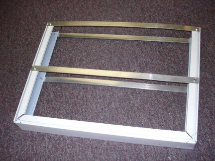 I then added some thin aluminum strips across the frame to help hold the pad in place against the force of the air flow.
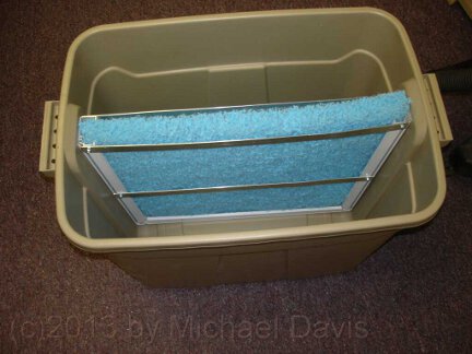 I then cut a piece out of the big blue pad to fit inside the frame. Here I am test-fitting the finished pad assembly in the tote again. Looking good!
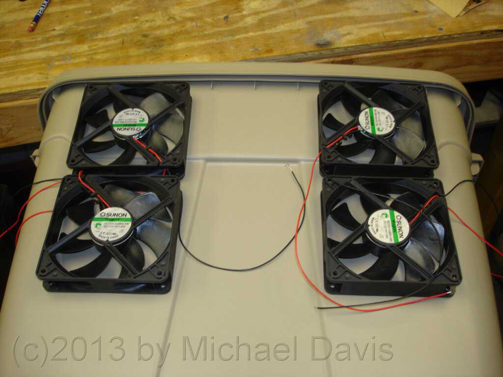
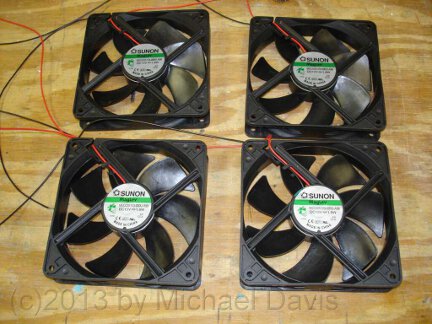 I needed some fans to move air through the swamp cooler. Fortunately my Brother is in the fan business. He donated four large 12V fans
to the project. These are five inch diameter (120mm) 12VDC fans made by Sunon. The part number is MEC0251V3-000U-A99. They move over
108 CFM each and are very quiet. They only cost about $10 each, if you don't have a brother willing to donate them.
I needed some fans to move air through the swamp cooler. Fortunately my Brother is in the fan business. He donated four large 12V fans
to the project. These are five inch diameter (120mm) 12VDC fans made by Sunon. The part number is MEC0251V3-000U-A99. They move over
108 CFM each and are very quiet. They only cost about $10 each, if you don't have a brother willing to donate them.
 I next marked out where I was going to mount the fans and holes that needed to be cut out. I put them near the top of the tote so there
would be room at the bottom for a water reservoir.
I next marked out where I was going to mount the fans and holes that needed to be cut out. I put them near the top of the tote so there
would be room at the bottom for a water reservoir.
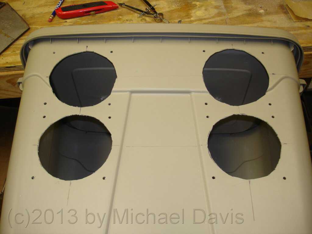
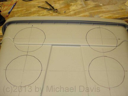 After locating where each fan would go, I drew circles with a compass to mark areas that needed to be cut out. The pencil lines from the
compass were nearly invisible on the surface of the plastic tote, so I went over them with a sharpie. I also marked out screw holes for
mounting the fans, but forgot to take a photo of it.
After locating where each fan would go, I drew circles with a compass to mark areas that needed to be cut out. The pencil lines from the
compass were nearly invisible on the surface of the plastic tote, so I went over them with a sharpie. I also marked out screw holes for
mounting the fans, but forgot to take a photo of it.
 Here I have cut out the air holes for the fans and drilled out the holes for the mounting screws. Cutting the large air holes was very easy.
I used a box cutter knife. The soft plastic of the tote cut very easily. I went slowly and carefully so as not to ruin the tote, or cut myself.
Wearing leather gloves while cutting is probably a good idea in case the knife slips.
Here I have cut out the air holes for the fans and drilled out the holes for the mounting screws. Cutting the large air holes was very easy.
I used a box cutter knife. The soft plastic of the tote cut very easily. I went slowly and carefully so as not to ruin the tote, or cut myself.
Wearing leather gloves while cutting is probably a good idea in case the knife slips.
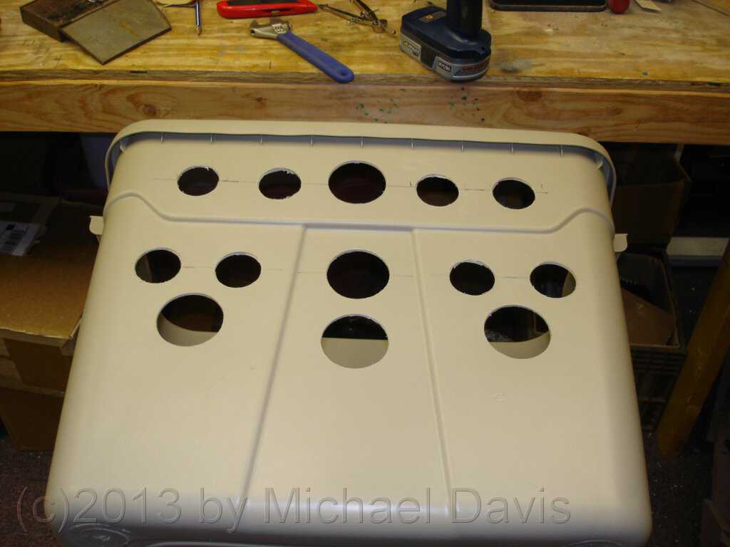
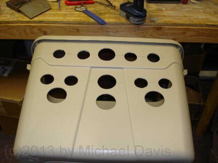 Here I have cut a bunch of air inlet holes in the tote on the side opposite the fans. I used two different size large hole saws to quickly
cut out a lot of holes. I was trying to open up as many holes as possible to increase airflow, but at the same time not weaken the tote too
much by cutting away too much plastic. I had noticed that cutting out the big holes for the fans had made that side of the tote weak and floppy.
I wanted to avoid that on this side. So that is the reason for the strange pattern of holes. Again, I bunched the holes near the top of
the tote to leave a space for a water reservoir at the bottom.
Here I have cut a bunch of air inlet holes in the tote on the side opposite the fans. I used two different size large hole saws to quickly
cut out a lot of holes. I was trying to open up as many holes as possible to increase airflow, but at the same time not weaken the tote too
much by cutting away too much plastic. I had noticed that cutting out the big holes for the fans had made that side of the tote weak and floppy.
I wanted to avoid that on this side. So that is the reason for the strange pattern of holes. Again, I bunched the holes near the top of
the tote to leave a space for a water reservoir at the bottom.
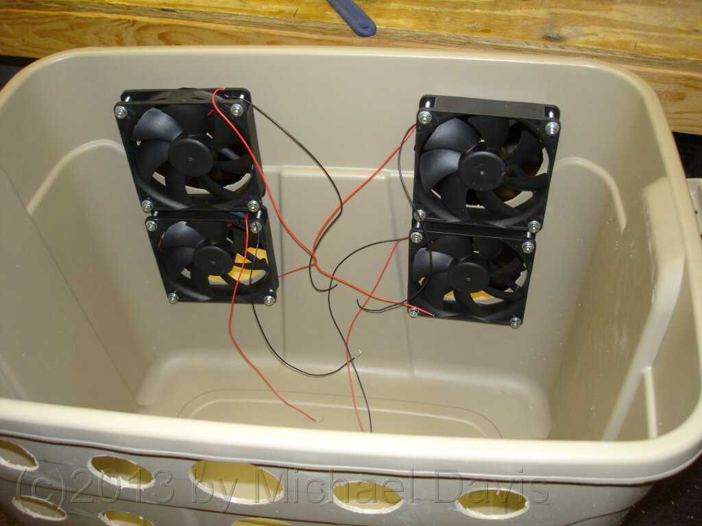
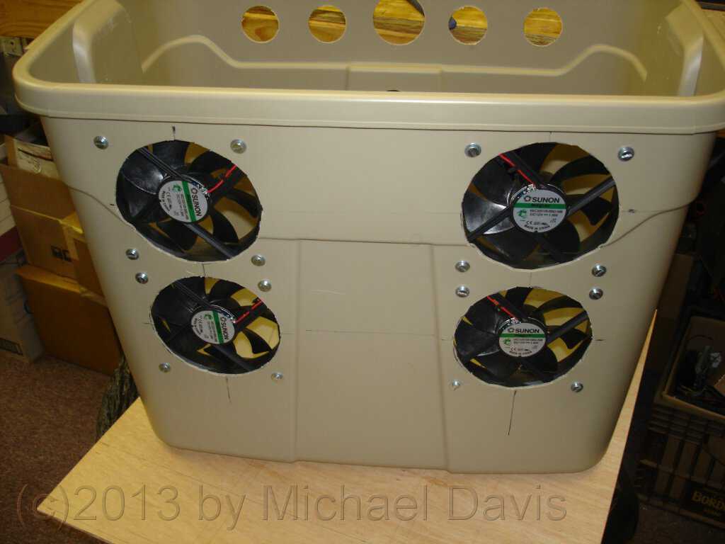
 Here is an inside view of the fans mounted in the tote. After mounting the fans, that side of the tote became rigid again. It had become quite
floppy after removing so much of the plastic for the big air holes. Right now the fan wires are just hanging all over the place. They will be
neatened up later.
Here is an inside view of the fans mounted in the tote. After mounting the fans, that side of the tote became rigid again. It had become quite
floppy after removing so much of the plastic for the big air holes. Right now the fan wires are just hanging all over the place. They will be
neatened up later.
 Here is a view from the outside with the fans mounted in the tote. Looks pretty good if I do say so myself. I think I need to get some wire
safety grills for the fans.
Here is a view from the outside with the fans mounted in the tote. Looks pretty good if I do say so myself. I think I need to get some wire
safety grills for the fans.
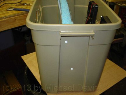 Here I have permanently mounted the frame holding the pad in the tote. I made a bit of a mistake when I built the frame. It is a little bit
too tall. The lid would not snap onto the tote with the frame inside. I can't believe I forgot to test that. The solution was to simply angle
the frame diagonally a little bit. Check out the two mounting screws in the side of the tote holding the frame in place. You can see the angle
it is tipped at. The mounting screws were placed high enough to prevent water from the reservoir at the bottom from leaking out.
Here I have permanently mounted the frame holding the pad in the tote. I made a bit of a mistake when I built the frame. It is a little bit
too tall. The lid would not snap onto the tote with the frame inside. I can't believe I forgot to test that. The solution was to simply angle
the frame diagonally a little bit. Check out the two mounting screws in the side of the tote holding the frame in place. You can see the angle
it is tipped at. The mounting screws were placed high enough to prevent water from the reservoir at the bottom from leaking out.
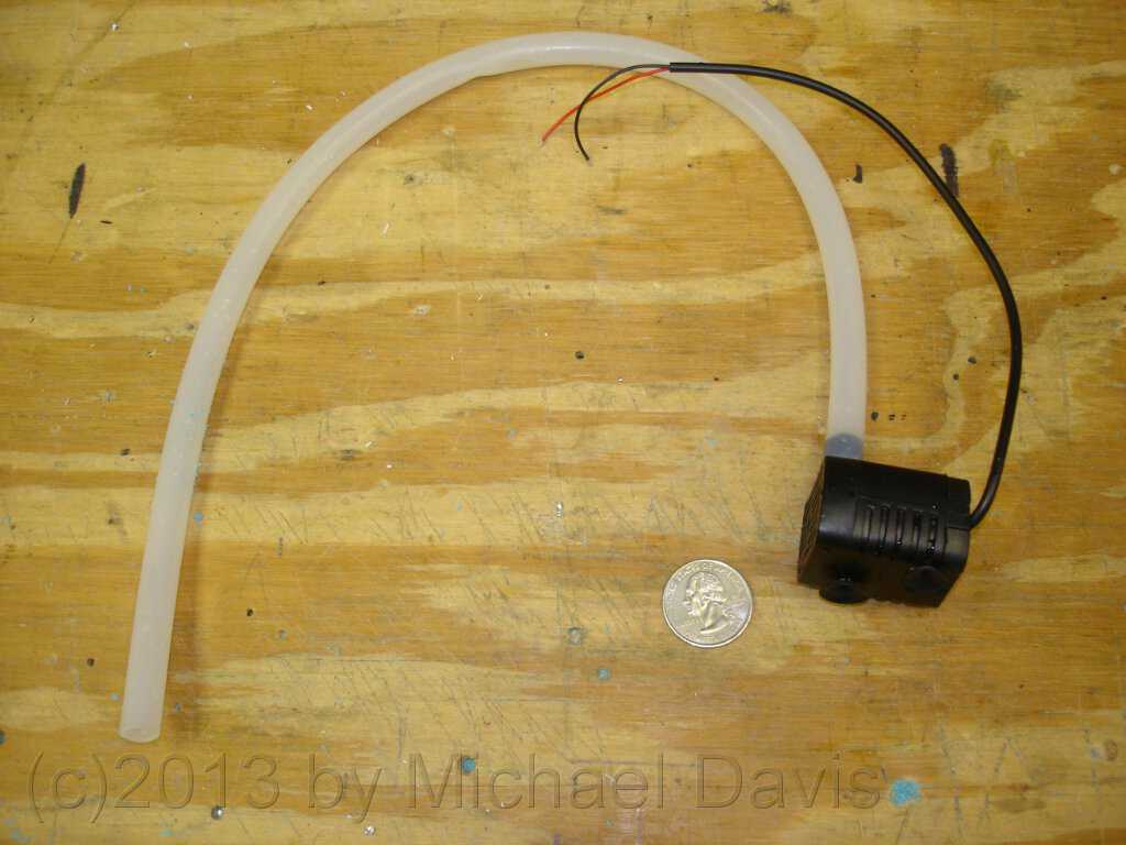
 I bought a tiny little 12 VDC fountain pump on Ebay. It only cost a few bucks. It is only capable of lifting water about 18 inches, but that is
enough for this project. It has an impressively high flow rate for such a tiny pump. It is also very quiet, which is nice.
I bought a tiny little 12 VDC fountain pump on Ebay. It only cost a few bucks. It is only capable of lifting water about 18 inches, but that is
enough for this project. It has an impressively high flow rate for such a tiny pump. It is also very quiet, which is nice.
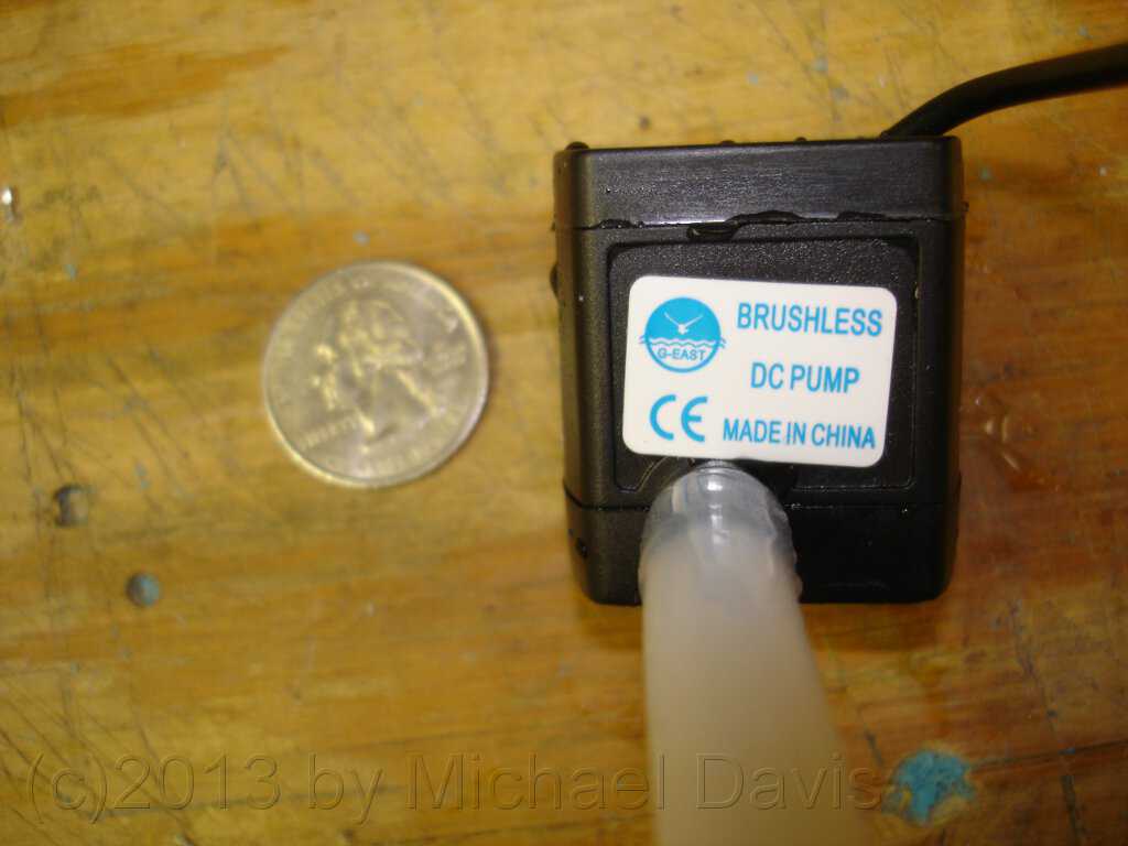
 Here is another view of the very tiny pump next to a quarter coin for comparison. the pump has suction cups on the bottom that supposedly should
hold it to the bottom of the tote. I have found that after only a fairly short period of operation the cups let go and the pump tends to float up
and suck air. It is easy to tell when the pump is sucking air. It goes from being very quiet to making horrible gurgling noises. Attaching a
fishing weight to the pump (not shown) is one solution I found to keep it submerged. A more permanent solution I may look
into is adding a bracket to the bottom of the pad frame to hold the pump down.
Here is another view of the very tiny pump next to a quarter coin for comparison. the pump has suction cups on the bottom that supposedly should
hold it to the bottom of the tote. I have found that after only a fairly short period of operation the cups let go and the pump tends to float up
and suck air. It is easy to tell when the pump is sucking air. It goes from being very quiet to making horrible gurgling noises. Attaching a
fishing weight to the pump (not shown) is one solution I found to keep it submerged. A more permanent solution I may look
into is adding a bracket to the bottom of the pad frame to hold the pump down.
 A way is needed to distribute the water across the whole length of the top of the pad so it will trickle down and wet the entire pad. There are
several ways to do it. The water could be pumped up to a perforated trough running the length of the top of the pad. Or the method I chose which
is to use a spray bar. My spray bar is nothing more than a length of PVC pipe with a lot of holes drilled in it to let the water spray out. it
is a technique I am familiar with and have used successfully with my recirculating sluice boxes I use for gold mining.
A way is needed to distribute the water across the whole length of the top of the pad so it will trickle down and wet the entire pad. There are
several ways to do it. The water could be pumped up to a perforated trough running the length of the top of the pad. Or the method I chose which
is to use a spray bar. My spray bar is nothing more than a length of PVC pipe with a lot of holes drilled in it to let the water spray out. it
is a technique I am familiar with and have used successfully with my recirculating sluice boxes I use for gold mining.
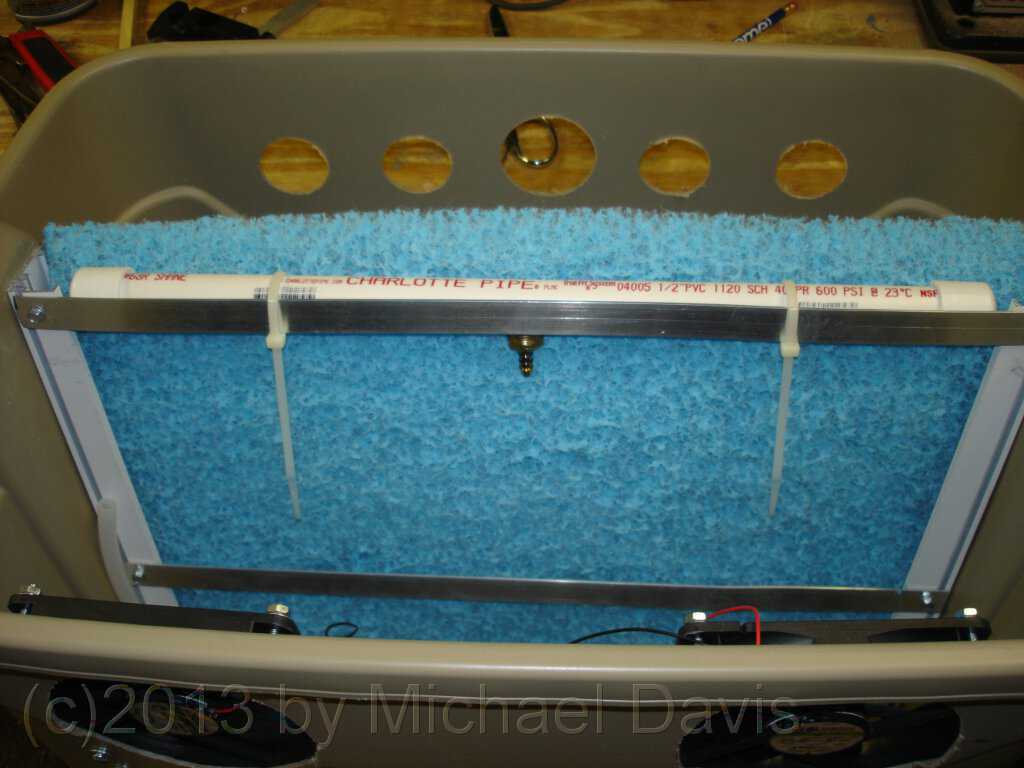
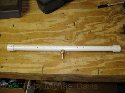
The spray bar is a length
of 1/2 inch PVC pipe the same length as the pad. Caps were installed on each end. small holes were drilled about 1 inch apart along its entire length.
A lager hole for a brass hose barb fitting was drilled in the middle of the spray bar. All parts were friction fitted together. Leaks are not a problem
since they just put more water on the pad. The hose from the pump will attach to the hose barb.
 Here the spray bar has been wire-tied to the top of the frame holding the pad. The spray bar is oriented with all the holes facing the pad. The
hose leading to the pump has not yet been attached to the hose barb.
Here the spray bar has been wire-tied to the top of the frame holding the pad. The spray bar is oriented with all the holes facing the pad. The
hose leading to the pump has not yet been attached to the hose barb.
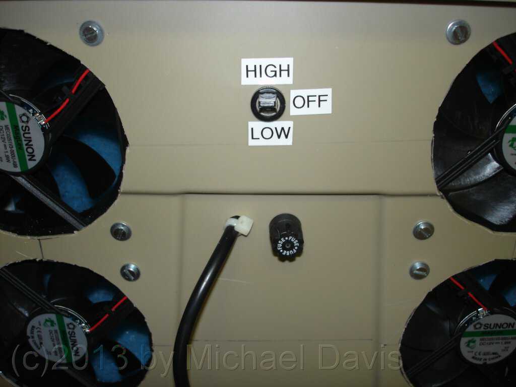
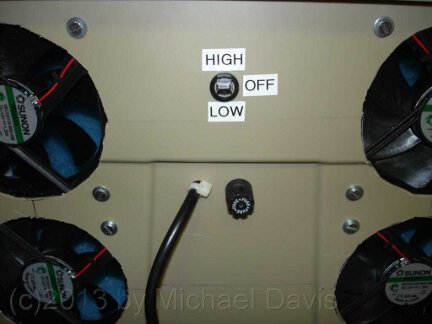 Here is a photo showing the outlet side of the finished unit. A DPDT center off power switch has been installed to give high and low power levels on the
output. This is achieved by only running two fans on the low setting, and running all four on the high setting. The photo also shows a fuse holder and
the power cord entering the tote. Notice that everything is mounted quite high on the tote to keep it clear of the water reservoir in the bottom.
Here is a photo showing the outlet side of the finished unit. A DPDT center off power switch has been installed to give high and low power levels on the
output. This is achieved by only running two fans on the low setting, and running all four on the high setting. The photo also shows a fuse holder and
the power cord entering the tote. Notice that everything is mounted quite high on the tote to keep it clear of the water reservoir in the bottom.
I really do need to put guards on those fans.
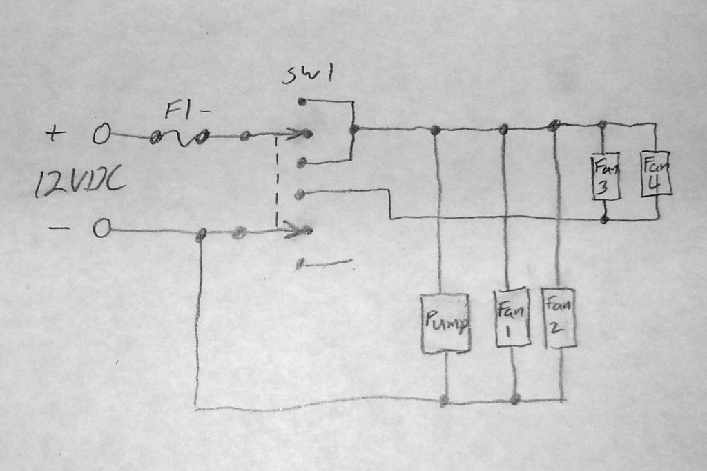
 Here is a schematic of how the swamp cooler is wired. It is pretty simple. SW1 is a double-pole, double-throw, center off switch. As you can see
from the schematic, the pump and fans 1 and 2 will always run when the switch is in either on position. Fans 3 and 4 only run when the
switch is in the "high" position. I included a 3 Amp slow-blow fuse in the circuit for protection.
Here is a schematic of how the swamp cooler is wired. It is pretty simple. SW1 is a double-pole, double-throw, center off switch. As you can see
from the schematic, the pump and fans 1 and 2 will always run when the switch is in either on position. Fans 3 and 4 only run when the
switch is in the "high" position. I included a 3 Amp slow-blow fuse in the circuit for protection.
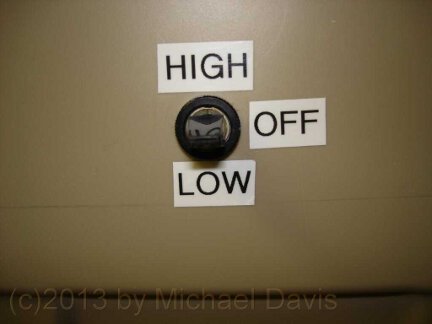 Here is a close-up of the power switch showing the high, low and center off positions. I labeled them using my Brother Label Maker to give it a
semi-professional looking finish.
Here is a close-up of the power switch showing the high, low and center off positions. I labeled them using my Brother Label Maker to give it a
semi-professional looking finish.
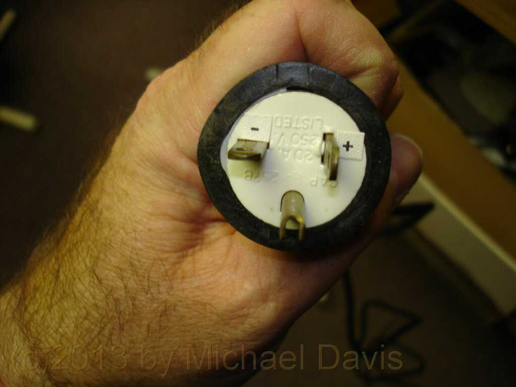
 My remote cabin is off-grid. I use a home-made wind turbine and
solar panels on a home-made tracking system to power the cabin. It is a 12VDC based system. I am in
the process of wiring the cabin
with 12VDC outlets. I am using plugs of this configuration for all my 12V appliances. Because of the different prong configuration, there is no chance of
accidentally plugging them into a live 120V outlet from an inverter. So the swamp cooler was also wired to plug into a 12VDC outlet.
My remote cabin is off-grid. I use a home-made wind turbine and
solar panels on a home-made tracking system to power the cabin. It is a 12VDC based system. I am in
the process of wiring the cabin
with 12VDC outlets. I am using plugs of this configuration for all my 12V appliances. Because of the different prong configuration, there is no chance of
accidentally plugging them into a live 120V outlet from an inverter. So the swamp cooler was also wired to plug into a 12VDC outlet.
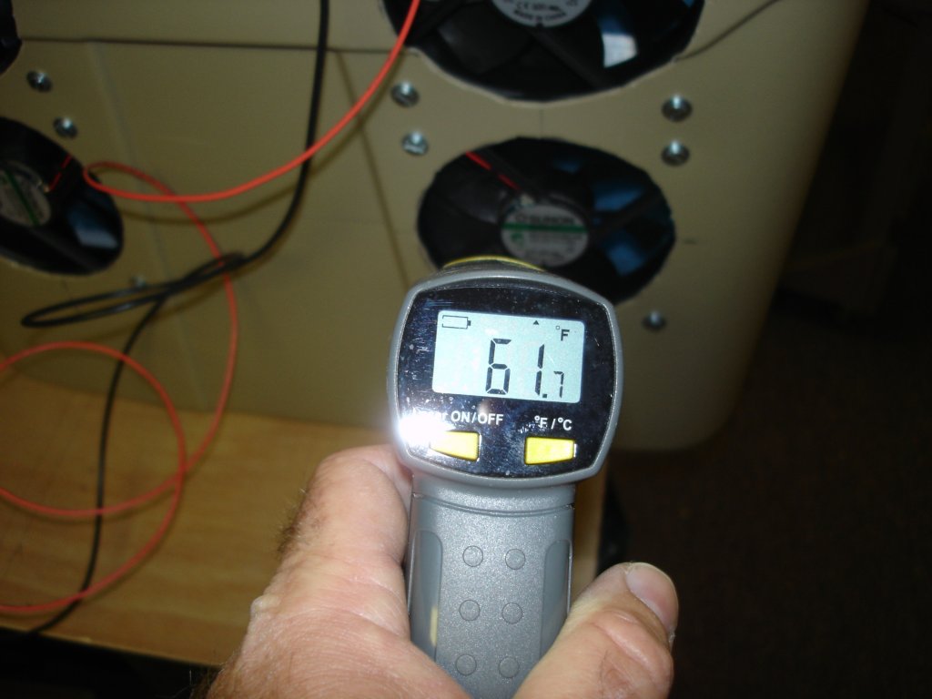
 Here is an early test of the swamp cooler done inside my air-conditioned workshop. The air temperature in the room was only about 76F, with relatively high humidity.
but I wanted to test out the nearly finished unit. So I filled it with water and fired it up. As you can see, after running for a while, the outlet
temperature got down to 61F. Not bad, considering that these are less than ideal conditions for running a swamp cooler.
Here is an early test of the swamp cooler done inside my air-conditioned workshop. The air temperature in the room was only about 76F, with relatively high humidity.
but I wanted to test out the nearly finished unit. So I filled it with water and fired it up. As you can see, after running for a while, the outlet
temperature got down to 61F. Not bad, considering that these are less than ideal conditions for running a swamp cooler.
I was really eager to use my new swamp cooler at my cabin on my remote Arizona property. Wouldn't you know it. When I finally I got out there, the weather
was cool. I didn't really need it. But I just had to try it out. I built a little shelf in front of the South-facing window in my cabin. My plan was to open
the window part way to allow some dry outside air to be pulled into the swamp cooler. There would also naturally be some recirculation of room air around
to the inlet side. I figured that recirculation would further chill already chilled air, and drive the temperature in the cabin even lower. The humidity
in my area of Arizona is so low that I figured the air could recirculate several times without becoming saturated. I set up my thermocouple probes to test
how well it was working and started the unit up.
 It wasn't a terribly hot day, but it was very dry, so I figured the unit should function well. As you can see from the photo, the inlet temperature was
only 76.6F. The outlet temp was
62.0F. So I got a drop of over 14F. That will come in handy in the Summer when the temperature will be in the 80s and occasionally the 90s.
It wasn't a terribly hot day, but it was very dry, so I figured the unit should function well. As you can see from the photo, the inlet temperature was
only 76.6F. The outlet temp was
62.0F. So I got a drop of over 14F. That will come in handy in the Summer when the temperature will be in the 80s and occasionally the 90s.
I found during my testing
that the outlet temperature will get lower over time as the water in the reservoir chills down. After an hour or two of operation the reservoir water is
quite cold. My swamp cooler might just be able to double as beverage chiller. Maybe next time I will stash a few cans of a tasty beverage in the reservoir
and test how cold they get, all in the name of science of course.
So my home-made swamp cooler only got the briefest of tests on this trip to my cabin. It will get a more thorough workout on future trips. On the whole I am
very happy with it, so far. Time will tell how well it holds up. Updates and modifications will be posted here as they happen.